
Google Patents a Split-Component Design to Make Wireless Charging More Efficient
Wireless charging pads often struggle when your phone isn't perfectly centered. Google has filed a patent describing a way to spread the charging work across multiple coil-and-capacitor pairs, potentially making power transfer more forgiving and more efficient.
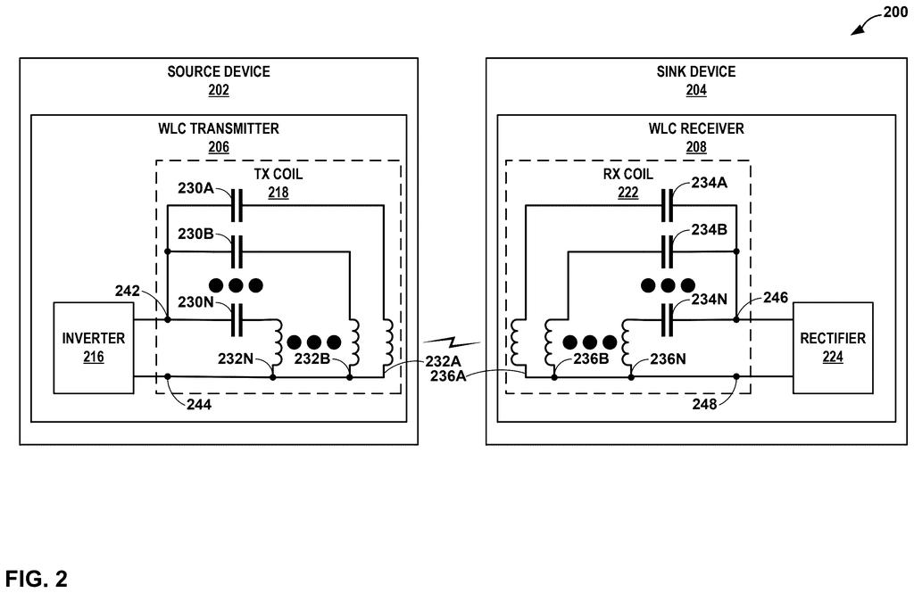
What Google's split-coil wireless charging actually does
Why does wireless charging sometimes feel so finicky? Place your phone even slightly off-center on a pad and it charges slowly, or not at all. That inefficiency comes down to how well the charger's magnetic field lines up with the coil inside your phone.
Google's patent describes a charger built from several smaller coil-and-capacitor pairs all working in parallel, rather than one big single unit. Think of it like splitting a single water pipe into several smaller pipes: the flow becomes easier to manage, and you're less dependent on any one path. All the pairs receive or send the same electrical signal together, so the system acts as one but is physically distributed.
The design also includes extra adjustable capacitors that can be switched in or out. That lets the charger tune itself on the fly, which can help maintain the right resonant frequency (the electrical "sweet spot" that makes wireless power transfer most efficient) even as conditions change.
… one or more supplemental resonant banks that each include capacitors switchably in parallel with capacitors of the plurality of capacitor and wireless charging coil series pairs …
Translation: Extra capacitors that can be toggled on to tune the charging circuit's frequency.
How the parallel coil-capacitor pairs share one signal
At the heart of wireless charging is a resonant circuit: a coil and a capacitor tuned to vibrate at the same electrical frequency, which lets energy jump across an air gap efficiently. Google's patent restructures that circuit into multiple capacitor-and-coil series pairs wired in parallel between two common connection points.
Having several pairs in parallel rather than one large coil can lower the overall electrical stress on each component and may allow the charger to cover a larger or more irregular area. A single shared driver circuit sends one common signal across all the pairs simultaneously, so coordination between them is built into the architecture from the start.
The independent claim adds supplemental resonant banks: extra capacitors that can be switched in or out of the circuit. This is essentially a tuning dial. By adding or removing capacitance, the system shifts its resonant frequency, which matters because real-world conditions (temperature, the device being charged, alignment) can push a circuit off its ideal operating point.
- Multiple coil-capacitor pairs share one driver or receiver circuit
- All pairs are wired in parallel, spreading electrical load
- Switchable extra capacitors allow real-time frequency tuning
a driver circuit configured to drive the plurality of capacitor and wireless charging coil series pairs with a first common signal …
Translation: The internal hardware component that sends power out through the charging coils.
What this means for wireless charger range and heat
For you as a user, the most direct payoff would be a charger that works reliably even when your phone is not perfectly placed. Distributing the magnetic field across several coil pairs could reduce the "dead zones" that make current pads frustrating. It may also reduce heat, since each individual coil carries less current than one large coil doing all the work alone.
The switchable capacitor banks add a layer of adaptability. A charger that can retune itself to different devices or ambient temperatures is less likely to charge at a crawl when conditions aren't ideal. Whether Google applies this to a consumer charging pad, a Pixel phone receiver coil, or something else entirely, the underlying benefit is the same: fewer moments where you pick up your phone in the morning and discover it barely charged overnight.
This is the 24th Google filing we've tracked in our cell phone coverage since May, adding to work like one adjusting chip power by task and one on headphone head movement.
The frustrating part of wireless charging has always been the gap between what you expected and what you got: a phone you left on the pad overnight, still half-dead in the morning. Google's patent addresses exactly that failure by splitting the charging hardware into multiple smaller, parallel units that work together, so if one path underperforms, the others carry the load.
The practical result is a charger that can adjust itself to maintain a strong, consistent connection rather than delivering an uneven trickle. A person would notice this most on the mornings they don't notice anything at all, because their phone is simply full.
This is careful, focused engineering aimed at a specific daily annoyance. It matters because the failure it prevents is one people have accepted for years.
There are more where this came from
We read every patent application Big Tech publishes and send you the ones worth knowing. Plain English, free, every week.
The drawings
15 drawing sheets from US 2026/0280347 A1 · click any drawing to enlarge


Want this weekly breakdown for a company we don't cover? Patentlyze Pro →
Be the first to weigh in