
Sony Files Patent to Keep Distance-Measuring Lights Equally Bright
When more lasers in a grid switch on at once, each one gets a little less power from the shared wiring. Sony's patent filing counts the lasers that are firing and corrects for it.
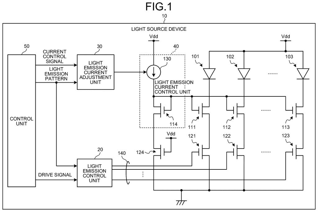
What Sony's laser-grid patent actually fixes
You're pointing a depth sensor at a room, and it's firing a grid of tiny lasers to work out how far away everything is. Some scans light up every laser. Others light up only a few.
Here's the catch: the wiring that feeds those lasers is partly shared, so lighting more of them steals a little power from each one. The same laser can end up slightly dimmer or brighter depending on how many of its neighbors are on.
Sony's patent filing adds a small controller that counts how many lasers are about to fire and nudges the power to make up the difference. In the filing's example, a scan with one laser gets 5% less current than a scan with ten, so the light output stays even either way. It also describes a second route: leave the power alone and make each light pulse slightly shorter instead.
… a light emission current adjustment unit that adjusts the light emission current according to the number of light emitting elements caused to emit light among the plurality of light emitting elements.
Translation: This part changes the electrical current depending on how many lights are currently turned on.
How Sony corrects power by counting active lasers
The device is a grid of lasers (the filing names vertical cavity surface emitting lasers, a flat type of laser chip). Each laser has its own on/off switch and its own current limiter, a transistor (a tiny electronic valve) that caps how much electricity flows through it. A current mirror (a circuit that copies one reference current out to many places) sets that cap for every laser.
The trouble is the shared ground wire. Every wire has a little resistance, and when many lasers fire at once, their combined current causes a bigger voltage drop along the shared stretch. That shrinks the voltage driving each limiter, so each laser gets slightly less current than intended. Fewer lasers on means a smaller drop and more current per laser.
The fix is a light emission current adjustment unit. It reads the light pattern to count the lasers about to fire, looks up a correction in a stored table, and changes the reference current. The filing also describes variations:
- Shortening the light pulse instead of changing the current (for one laser, the example trims the pulse by 5%).
- Splitting the grid into regions, each with its own correction and its own current mirror.
- Adjusting the overcurrent alarm threshold according to the laser count.
The claims also cover a distance measurement device that times how long the light takes to bounce off an object and return to a sensor (called time of flight).
A change in a light quantity due to a change in a light emission current of a light emitting element is reduced.
Translation: The invention prevents the brightness from fluctuating when the electrical current shifts.
Why steadier laser light matters for depth sensing
Depth sensors that time light bouncing off objects depend on the light they send out behaving predictably. If a laser grid gets brighter or dimmer just because of which lasers happen to be lit, the sensor's designers have one more source of variation to chase down. This filing handles that at the circuit level, before the light ever leaves the chip.
You would never see this feature. If it works, it shows up as a more consistent sensor in whatever device carries it, and as a simpler job for the engineers tuning it. The filing does not name a product, and it presents the correction as a stored table keyed to the number of active lasers, which is easy to calibrate and cheap to run.
That makes this Sony's 34th filing we've tracked since July in the self-driving sensing race, adding to earlier ones like one warning drivers via road projection and one catching camera timing failures.
You will never notice this circuit working, and that is the point. The failure it prevents is a laser sensor whose brightness shifts depending on how many lasers happen to be lit, which could make its readings vary from one scene to the next.
If you use any device with a depth sensor, the benefit would show up as fewer odd readings rather than a new feature. A correction table keyed to a laser count is a modest, practical answer to a wiring side effect.
Sony does not claim a dramatic gain, and the filing gives only a sample table. Treat it as careful housekeeping for the people building these sensors, with a small payoff for everyone else.
Get our take in your Top Stories
Liked this breakdown? Add Patentlyze as a preferred source on Google, and our plain-English take shows up more often in your Top Stories the next time Sony patent news breaks.
There are more where this came from
We read every patent application Big Tech publishes and send you the ones worth knowing. Plain English, free, every week.
The drawings
21 drawing sheets from US 2026/0342042 A1 · click any drawing to enlarge


Show the other 13 sheets


Want this weekly breakdown for a company we don't cover? Patentlyze Pro →
Be the first to weigh in