
Apple Files Patent for a Camera Sensor That Measures Each Pixel Two Ways
Apple's patent application gives every pixel in a camera sensor two ways to measure the same burst of light, one tuned for dim scenes and one for blinding ones. Both readings come from a single exposure.
What Apple's two-reading camera pixel actually does
Every time you snap a photo of a friend standing in front of a bright window, your phone has to pick a side. Expose for the face and the window turns into a white blob. Expose for the window and your friend turns into a silhouette.
This Apple patent application tries to skip that choice at the level of the individual pixel. Each tiny light-catching dot on the sensor gets two separate measurements from one shot. One is a careful, low-noise reading that works well in dim light but maxes out quickly. The other is rougher, but it squeezes bright light into a smaller range, so it keeps working long after the first reading has given up.
When the careful reading hits its ceiling, the camera switches to the rough one. In between, it can blend the two.
A high dynamic range camera device has an image sensor that implements readout circuitry to read out, for individual pixels of the sensor, two values that are based on two different types of charge carriers produced in response to a light exposure.
Translation: Apple's camera design captures two separate readings per pixel to handle very bright and dark areas at once.
How the pixel splits light into two signals
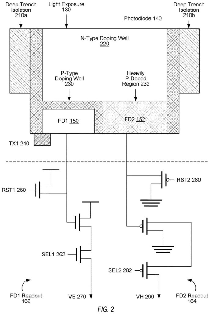
Each pixel contains a photodiode, a tiny part that turns light into electric current. In the main example, that light frees two kinds of electrical charge: electrons (negative) and holes (a positive charge, essentially the gap an electron leaves behind). Each kind is collected in its own storage spot, called a floating diffusion node.
The two spots are read out in different ways:
- Linear readout: the output rises in a straight line with the amount of light. It is clean and low in noise, but it fills up at a limit (called saturation). It uses a transfer gate, a switch that moves charge into the storage spot.
- Logarithmic readout: there is no transfer gate. A reset transistor lets a small leakage current flow, and the voltage it produces measures the stored charge. That compresses a huge range of brightness into a small range of voltage, at the cost of more noise.
The claims say the logarithmic value is used to build the image when the linear value passes a saturation threshold. The filing also describes weighted blending across several brightness tiers, and different thresholds for different pixels.
Because the logarithmic circuit varies from pixel to pixel, the filing describes a calibration step: compare both readings for the same test exposure, then correct the logarithmic one. The bright-light side is also read twice, before and after a reset, and the difference is used. The filing says the readout circuits can sit on a second chip, bonded to the first.
… a second readout circuitry of the pixel that does not employ a transfer gate for the FD 2 node, the second readout circuitry comprising a reset transistor controllable to: (i) allow a leakage current from the FD 2 node to measure an accumulated charge at the FD 2 node, and (ii) in response to a reset signal, pull the FD 2 node to a ground voltage to discharge the FD 2 node …
Translation: The second circuit uses a reset transistor to measure leaking charge and clear the node when needed.
Why this matters for your phone's bright-light shots
If this design ever reached a phone, the payoff would be photos and video where the bright sky and the shaded face both come out right, shot after shot. The filing says it needs only one exposure per frame, which allows faster readout and higher frame rates. That matters most for video, where there is no time to shoot extra frames and merge them.
The filing also points to battery life. It says the design needs no added power to stretch a pixel's range, so a phone could run longer between charges, carry a smaller battery, or run several cameras at once. Those are the filing's claims about its own design, and this is a patent application, not a product.
That makes this Apple's 44th filing we've tracked under our Display patent coverage since May, a group that includes applications like a foldable computer stand and fixing brightness bands near cutouts.
Scenes with deep shadows and bright highlights trip up every camera: the window behind a portrait, a sunset over a dark street, headlights at night. Every phone owner has run into this, so a fix built into the sensor chip itself is aimed at a target that matters.
The filing's answer matches the size of that target. Instead of shooting several photos and merging them, which the filing says slows readout and uses more power, each pixel reports twice from one exposure. The filing admits the bright-light reading is noisier. That is a fair price, since it only steps in when the main reading is already maxed out.
The catch is manufacturing. The design asks for a second chip in some versions and a calibration step for every pixel, because the bright-light circuits differ from one pixel to the next. That is hard to build, yet a gain in every photo and video clip would justify the effort.
Get our take in your Top Stories
Liked this breakdown? Add Patentlyze as a preferred source on Google, and our plain-English take shows up more often in your Top Stories the next time Apple patent news breaks.
There are more where this came from
We read every patent application Big Tech publishes and send you the ones worth knowing. Plain English, free, every week.
The drawings
10 drawing sheets from US 2026/0343113 A1 · click any drawing to enlarge


Show the other 2 sheets


Want this weekly breakdown for a company we don't cover? Patentlyze Pro →
Be the first to weigh in