
Sony Files Patent for Tiny Rubber Muscles That Flex on Electricity
Sony describes a rolled-up rubber tube that stretches and shrinks like a muscle when voltage hits it, and the trick is a tiny staircase cut into one end.
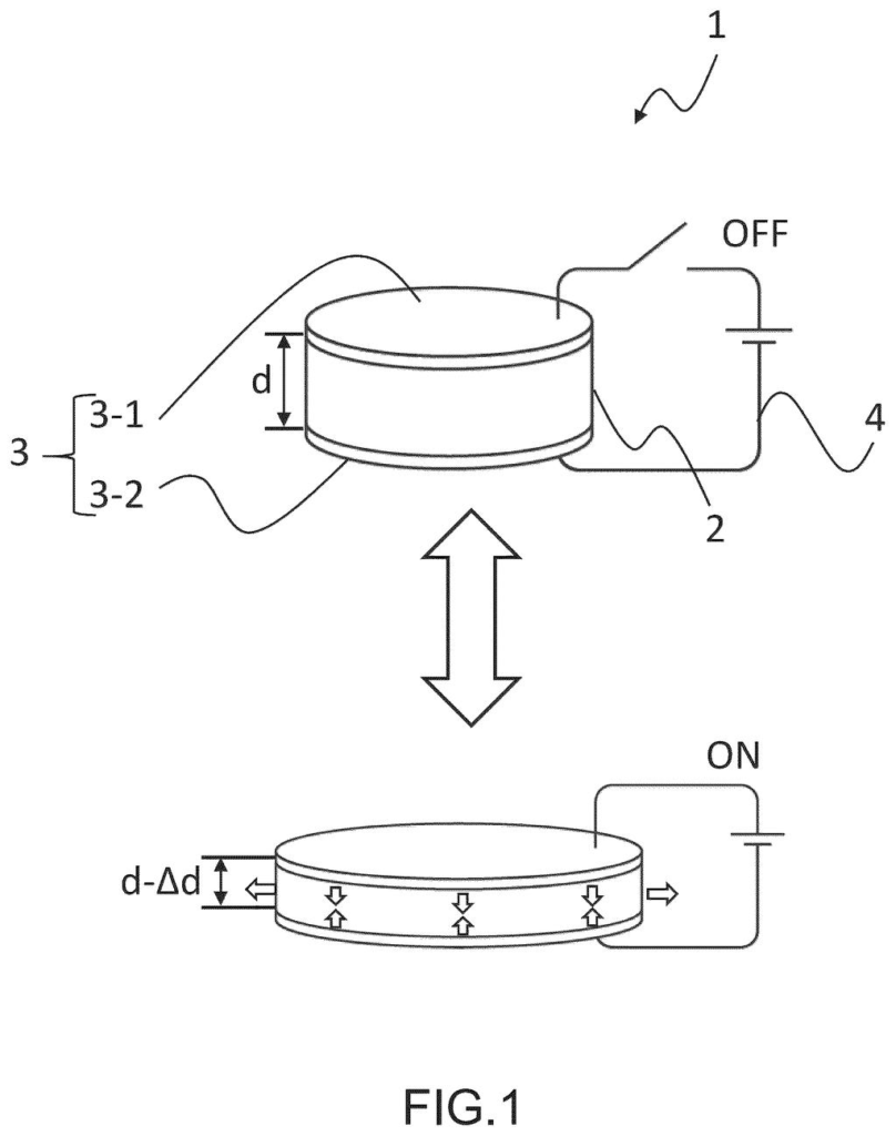
What Sony's rolled rubber muscle actually does
You press a button and it pushes back, firm one moment and soft the next, depending on what you're doing. Sony's patent application describes a tiny part that could create that kind of changing feel.
The part is a small tube made by rolling up thin sheets of stretchy rubber layered with electrodes (thin conductive coatings). Apply voltage and the tube gets longer or shorter, a bit like a muscle. The hard part is making it small: wires have to reach two electrodes packed into a very tight space, and if they touch, the part shorts out.
Sony's answer is to cut the sheet into a stepped shape before rolling it. One end of the tube ends up like a tiny staircase, with each electrode sitting on its own level, so the two stay apart. A cap with matching steps fits right in.
A rolled dielectric elastomer actuator, comprising a rolled body of a laminate including at least one pair of complimentary electrode layers and a dielectric elastomer layer, the rolled body including at least one stepped bottom surface.
Translation: Sony built a tiny flexible tube out of layers of stretchy material and electrodes with a unique stepped bottom.
How the stepped end keeps electrodes apart
The patent covers a rolled dielectric elastomer actuator: a rolled-up laminate (a stack of thin layers) of stretchy insulating rubber and pairs of electrode layers. When voltage is applied, the electrodes pull toward each other and squeeze the rubber thinner, so the roll changes length along its axis. Claim 1 adds that at least one end of the roll has a stepped bottom surface.
The steps are made on purpose. The sheet is cut so its edge has different levels, and once rolled, those levels become concentric rings (rings sharing a center) at the end of the tube. One electrode is exposed on one step and the other on a second step. Some versions add a third step that exposes no electrode at all. A cap carrying electrodes, shaped to match the steps, fits into the end, and insulating adhesive can sit between them.
The manufacturing method has three main moves:
- Stack electrode and rubber layers into a sheet, described as 200 μm thick or less in preferred versions.
- Cut the sheet's outline so the rolled end will have steps.
- Roll it around a core, such as a paper tube coated with water-soluble glue, then dissolve the glue and pull the core out.
Another version splits one electrode layer into separate comb-shaped electrodes that can be powered independently, which lets the roll bend as well as stretch.
The present disclosure provides a method for manufacturing a rolled dielectric elastomer actuator, the method including a rolling step to roll at least one pair of complimentary electrode layers and a dielectric elastomer layer around a core to obtain a rolled body …
Translation: The patent describes wrapping thin layers around a core to make these microscopic artificial muscles.
Why a tiny muscle matters for buttons and scopes
For you, the benefit would show up in controls that can change how they feel. The filing describes using the part in an operation input device, where it adjusts the resistance you feel when moving a button, wheel, ball or joystick. It also names the endoscope (a thin medical camera tube) as an example. The same rolled body can sense how much it is being squeezed by measuring capacitance (how much electric charge it can hold).
The filing's own argument is about size. Smaller actuators fit into more devices, but short circuits and poor connections get worse as parts shrink. Stepped ends address both: separate levels keep the electrodes apart, and the electrodes can be made larger. The filing also says the steps are easy to produce, since they come from how the sheet is cut before rolling.
Sony's ninth battery and power filing we've tracked since June follows work like equal-brightness distance lights and a clip-on phone fan.
If this works as described, you would never see the stepped end. What you would notice is a button or control that keeps working and can change its feel, because a single short circuit in a part this small would kill it.
It's a manufacturing filing, plain and specific, and it targets one clear failure: two electrodes sitting too close together. That counts for a lot when the part has to shrink to fit inside a handheld control or a medical scope.
The filing says nothing about a finished product, so the near-term effect on you is zero. The longer-term effect depends on whether adjustable-feel controls feel good enough that people want them.
Get our take in your Top Stories
Liked this breakdown? Add Patentlyze as a preferred source on Google, and our plain-English take shows up more often in your Top Stories the next time Sony patent news breaks.
There are more where this came from
We read every patent application Big Tech publishes and send you the ones worth knowing. Plain English, free, every week.
The drawings
24 drawing sheets from US 2026/0352125 A1 · click any drawing to enlarge


Show the other 16 sheets


Want this weekly breakdown for a company we don't cover? Patentlyze Pro →
Be the first to weigh in