
Samsung Files Patent to Keep a Slide-Out Phone Screen From Bulging at the Bend
Every phone with a slide-out screen has to bend its display around a tight curve, and the screen fights back. Samsung's filing answers by tilting the walls of the tracks the screen rides on.
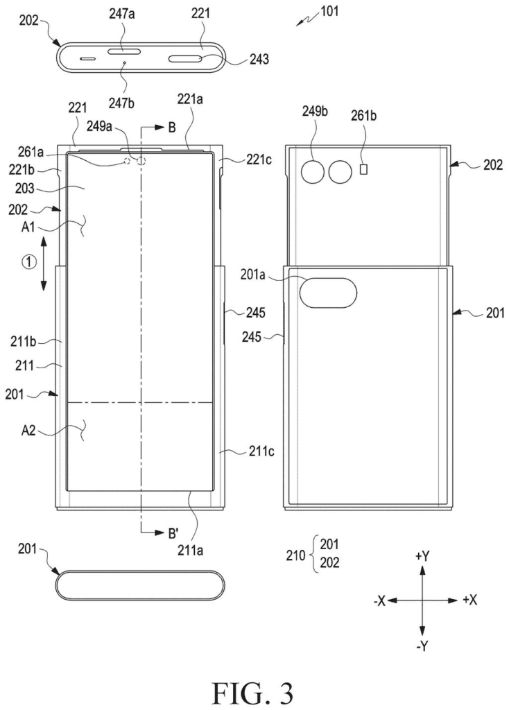
What Samsung's angled guide rails actually do
Every time a phone with a rollable screen slides open or shut, part of its display wraps around a tight curve inside the body. Screens don't love that. Bent material tries to spring back flat, which pushes the display outward, away from the curve.
Samsung's patent application describes a fix hidden in the tracks. Behind the screen sits a row of thin support bars, each with a small peg on both ends that rides in a groove along the side of the phone. Where the groove curves around the bend, its walls tilt slightly, which pulls the bars, and the screen attached to them, inward.
That inward pull cancels out the springback. The screen stays put instead of bulging, which protects the display and keeps the picture from warping.
… a multi-bar structure configured to support at least a portion of the flexible display; and a guide rail disposed in the housing and including a recess formed from an inner surface of the guide rail, the recess being formed to guide a movement of the multi-bar structure …
Translation: A system of bars and tracks supports the bendable screen as it moves.
How the tilted grooves push back on the screen
The claim covers a device whose body has two parts, one sliding between a retracted and an extended position, with a flexible display stretched across both. A multi-bar structure (a row of thin parallel support bars, a bit like a bicycle chain) backs part of the screen. A guide rail in the body has a groove that steers the bars, and part of that groove has at least one wall tilted away from the rail's inner surface.
Why tilt it? Where the display wraps around the curved edge of the frame, it develops a repulsive force (the screen trying to spring back flat) that pushes outward and can damage it or distort the picture. The tilted walls twist the small pegs on each bar's ends and push the bars the opposite way, from outside toward inside, canceling it out.
How the groove changes along the rail:
- Flat stretches have straight walls at about 270 degrees and add no extra push.
- The curved stretch tilts its two walls, with angles dipping to about 262 to 266 degrees on one side and rising to about 274 to 278 degrees on the other.
- The tilt is steepest at the middle of the bend, where the springback is strongest (the described bend radius is about 2 to 7 mm).
The filing also describes a reinforcing bulge where each peg meets its bar, plus ways to keep the bar ends snug against the groove so they don't wobble sideways.
… wherein the second housing portion is movable between a retracted position and an extended position relative to the first housing portion …
Translation: Part of the phone slides out to make the screen larger.
Why a slide-out phone screen needs this fix
If you ever use a phone whose screen slides out to get taller, the part that matters most is the bend you never see. Each time it opens or closes, the display wraps around a curve with a radius of about 2 to 7 mm, and a screen that bulges there could show a warped picture or get damaged. Samsung's design aims to fix that with the shape of the track alone.
For Samsung, the filing is about durability in a category where the screen is the whole selling point. Rollable displays only work if the moving parts survive daily use, and this patent application targets one specific failure point. It describes no product, so treat it as an engineering answer to a known problem.
Samsung's 91st filing we've tracked in our foldable phone patents since May follows work on protective screen edge coatings and moving apps from the fold.
Every fix has a bill, and this one's is visible in the filing itself. To push the screen back, the tilted walls twist the small pegs at the ends of each support bar. Twisting the same tiny parts every time you open and close the phone is a wear problem, which is why the patent adds a reinforcing bulge and a stepped shoulder where each peg meets its bar.
Tight tolerances are the other cost. The tilt changes only a few degrees along the curve (the filing gives 262 to 278 degrees against a flat 270), so the grooves have to be cut precisely. A rail cut slightly off would either wobble or bind, and keeping the bar ends snug takes careful manufacturing.
The trade reads as worth it. Springback is the central hazard of a screen that bends around a tight curve, and fighting it with the shape of a track is a passive fix with no extra electronics to fail. A little more stress on small parts is a fair price for a screen that stays flat.
Get our take in your Top Stories
Liked this breakdown? Add Patentlyze as a preferred source on Google, and our plain-English take shows up more often in your Top Stories the next time Samsung patent news breaks.
There are more where this came from
We read every patent application Big Tech publishes and send you the ones worth knowing. Plain English, free, every week.
The drawings
15 drawing sheets from US 2026/0333595 A1 · click any drawing to enlarge


Show the other 7 sheets


Want this weekly breakdown for a company we don't cover? Patentlyze Pro →
Be the first to weigh in