
Mobileye Files Patent for a Car Radar That Sees Sharper With Fewer Antennas
Mobileye's new filing lets stray signal noise creep up at wide angles on purpose, because the antennas themselves already hush those angles. That trade lets a small antenna row keep a beam about 4 degrees wide.
What Mobileye's hybrid radar antenna actually does
A car's radar is scanning a highway at night. Straight ahead sits a stalled truck. Off to one side, a guardrail bounces back signal of its own, and the radar has to tell the two apart.
Radar does this with a row of small antennas working as a team, and how that row is spaced decides how sharp the picture is. Evenly spaced rows give quiet, clean readings but a blurry view. Unevenly spaced rows give a sharp view but more stray noise. Mobileye's filing mixes both: some antennas on an even grid, the rest scattered.
The twist is that it fights the stray noise only where it matters, in the zone ahead of the car (about 30 degrees to each side in the example). Farther out, each antenna already weakens the signal, so the design lets the noise be. In the example, eight antennas produce a beam about 4 degrees wide.
a main beam between a first angle and a second angle; a first Side-Lobe (SL) region between the first angle and a third angle less than the first angle, wherein the first SL region comprises one or more first SL peaks below a predefined array factor value …
Translation: It carefully controls the main radar beam and its side lobes to focus the signal precisely.
How half the antennas are spaced unevenly
The claims cover an antenna array whose elements are placed to produce a specific array factor (the pattern of where the array sends and listens, before each single antenna's own pattern is added). That pattern has a main beam, the narrow cone that does the seeing, flanked by side lobes (weaker, unwanted bumps of sensitivity that can make a radar mistake a guardrail for something in its path).
The claimed shape has two zones of side lobes:
- Close to the main beam, side-lobe peaks stay below a set level. The examples put that level at least 8 to 10 dB below the main beam's peak (dB, or decibels, measures signal strength).
- Farther out, side-lobe peaks sit above a second, higher level, at least 3 dB higher.
- The main beam is under 10 degrees wide in the claims, with examples at 4 degrees or less, using signals above 70 GHz.
The filing gets there by placing some elements evenly and others unevenly. One claim puts at least 35 percent of the elements in the uneven group, and the main example splits eight elements half and half. The layout was tuned only across the field of view (about 30 degrees to each side). Beyond that, each antenna's own weak output keeps the true side lobes more than 30 dB down.
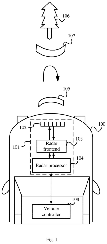
Other claims wrap the array into a radar system with transmit and receive antennas plus a processor, and into a vehicle whose controller acts on the radar's readings.
… an antenna array may include a plurality of antenna elements arranged according to an array arrangement configured to provide a predefined array factor including a main beam between a first angle and a second angle …
Translation: The radar uses a specific layout of antenna elements to shape how the radio waves travel.
Why a cheaper car radar array matters
For you, the payoff would show up in how well a car's radar tells things apart. A beam about 4 degrees wide can separate a stalled truck from a guardrail or a motorcycle in the next lane, and the filing says it can get there with few antennas (eight in the main example). Fewer antennas can mean lower cost, a smaller package, less power and less computing, all of which the description names as goals.
Radar is a main sensor in driver assistance and self-driving systems because it keeps working in nearly all weather, and Mobileye builds technology in that space. The filing also describes a layout with two transmit columns and one receive row, aimed at cutting false alarms from signals that bounce around. It is an application, so nothing here says when, or whether, it ships.
This is the tenth Intel filing we've tracked since September in our self-driving sensing race watchlist, following earlier applications on laser sensor interference and fixing map section gaps.
Every antenna design pays for something, and this one pays at wide angles. It stops caring about stray noise beyond roughly 30 degrees to each side and trusts each antenna's own weak output to keep that noise down. That works for a radar that stares forward. A radar watching a wide arc, such as one at a car's corner, would lean on that safety net far more, and the filing's numbers would need rechecking.
There is a second cost in the processing. The description leans on special maximum likelihood processing (a method that tests many possible answers and picks the best fit) to squeeze out extra improvement from the evenly spaced part, which means more work for the chip behind the antennas.
Still, the trade reads as a good one for forward-looking radar. Giving up quiet at angles the radar rarely cares about buys a beam about 4 degrees wide from eight antennas, a sharper view for less hardware.
Get our take in your Top Stories
Liked this breakdown? Add Patentlyze as a preferred source on Google, and our plain-English take shows up more often in your Top Stories the next time Intel patent news breaks.
There are more where this came from
We read every patent application Big Tech publishes and send you the ones worth knowing. Plain English, free, every week.
The drawings
19 drawing sheets from US 2026/0338947 A1 · click any drawing to enlarge


Show the other 11 sheets


Want this weekly breakdown for a company we don't cover? Patentlyze Pro →
Be the first to weigh in