
Nvidia Patents a System That Calibrates Sensors by Watching What They Detect
Keeping a camera or lidar sensor perfectly calibrated is tedious work that usually requires special targets and a technician. Nvidia's new patent describes a system that figures out calibration errors on its own, just by watching how the sensor sees ordinary objects in the real world.
How Nvidia's auto-calibration uses object shapes
Imagine you hang a picture on a wall, step back, and notice it looks slightly tilted. You adjust it a little, check again, and keep nudging until it looks right. Nvidia's patented system does something similar for the cameras and sensors on self-driving vehicles and robots.
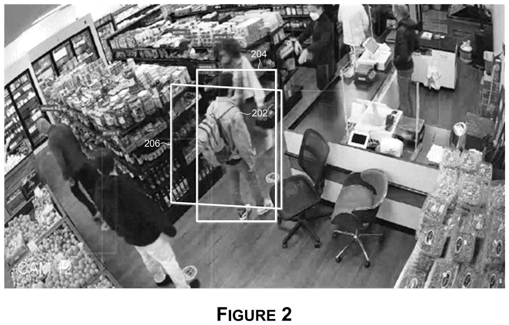
When a sensor captures a scene, the system looks at the bounding boxes it draws around detected objects (the little rectangles you see in object-detection demos). If the sensor is even slightly miscalibrated, those boxes will be in the wrong position or the wrong size. The system generates candidate adjustments, checks whether the boxes look more accurate, and keeps iterating until the boxes match what physics says they should look like.
The end result is a calibration parameter set that corrects the sensor without anyone needing to hold up a checkerboard target or run a special test drive. The process runs until the error drops below a set threshold or stops improving.
iteratively generating one or more sets of candidate calibration parameters for the sensor; generating one or more sets of candidate bounding shapes …
Translation: It tests multiple possible calibration settings by creating trial shapes around detected objects.
How the bounding-box comparison loop converges
The system works by comparing two things: the bounding shapes (rectangles or 3D boxes) that the sensor's object-detection model actually draws around detected objects, and the bounding shapes that should appear if the sensor were perfectly calibrated.
How the optimization loop works:
- The system builds a dataset of sampled bounding shapes from real detections the sensor has already made.
- It then searches a "parameter space" (a mathematical range of possible calibration settings, like angle offsets or lens distortion values) by generating sets of candidate calibration parameters.
- For each candidate set, it projects or transforms the sampled bounding shapes using those parameters, producing candidate bounding shapes.
- It measures the difference between the candidate shapes and the reference shapes. When that difference falls below a first threshold or the improvement stalls (level of convergence), the current candidate set is promoted to the final estimated calibration parameters.
The hardware target is described as "one or more processors comprising processing circuitry," which covers GPUs, CPUs, and dedicated inference chips equally. Once the parameters are found, the system feeds them back to the sensor to correct its output going forward. No physical calibration targets, no manual measurements.
A parameter space may be searched for estimated calibration parameters for the sensor using an optimization process.
Translation: The system automatically searches through possible adjustments to find the best calibration.
What this means for self-driving and robotics sensors
For self-driving vehicles and autonomous robots, sensor calibration drifts over time as hardware warms up, vibrates, or ages. Today, catching that drift often means taking the vehicle out of service for a manual calibration check. A system that self-calibrates from live detections could keep sensors accurate continuously, reducing downtime and improving safety margins.
Nvidia's steady investment in autonomous-vehicle sensor work shows up repeatedly in its patent filings. For anyone building on Nvidia's Drive or Isaac platforms, a built-in automatic calibration pipeline could lower the engineering overhead of deploying fleets of camera- or lidar-equipped machines in the real world.
This is the 54th Nvidia filing we've tracked since May on our self-driving sensing watchlist, building on earlier applications like one on detecting hidden objects and one on radar speed tracking.
Claim 1 is broad in the way that matters most: it covers any processor running this iterative bounding-shape comparison loop, without tying itself to a specific sensor type, object category, or optimization algorithm. That breadth means competitors couldn't easily sidestep it by swapping cameras for lidar or changing the search method.
The practical scope is real but not unlimited. The claim requires that the bounding shapes come from an object-detection step, so calibration approaches that don't involve detection-style bounding boxes sit outside it. That's a meaningful limitation, not just a technicality.
If granted as written, this claim would give Nvidia a strong position over any pipeline that uses detection outputs to auto-calibrate a sensor, which is exactly the direction the autonomous-vehicle industry has been heading. Whether the prior art holds up is the open question, but the claim itself is tightly reasoned.
There are more where this came from
We read every patent application Big Tech publishes and send you the ones worth knowing. Plain English, free, every week.
The drawings
9 drawing sheets from US 2026/0268524 A1 · click any drawing to enlarge


Want this weekly breakdown for a company we don't cover? Patentlyze Pro →