
Microsoft Patents Game Controller Scroll Wheels Built to Free Up Space Inside
Microsoft has filed a patent application for game controller scroll wheels that move their sensor out to the end of a long rod. The space that frees up inside holds a glowing light and, in the filing's example, an audio jack sitting between two wheels.
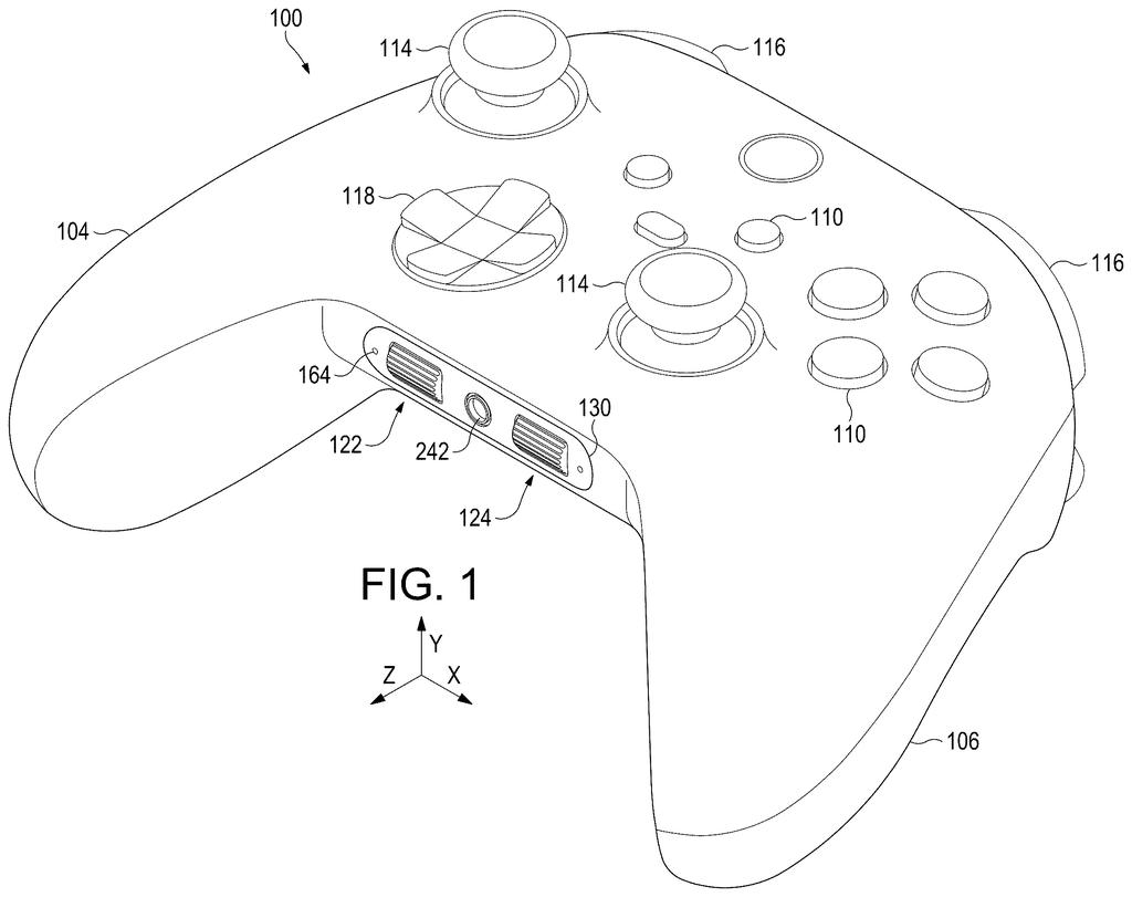
What Microsoft's thumb scroll wheels actually do
A modern game controller is packed tight: buttons, thumbsticks, bumpers and a direction pad all share a plastic shell about the size of your hands. There is very little spare room for anything new, like a scroll wheel for your thumb.
Microsoft's patent application tackles that squeeze with a rearrangement. A scroll wheel needs a sensor that counts how far it has turned, and normally that sensor sits right beside the wheel. Here, the wheel sits on a longer rod, and the sensor is moved out to the end of it, outside the main case around the wheel.
That frees up the space next to the wheel for other parts. The filing shows a small light that glows through a tiny window, and an audio component with a headphone-style jack sitting between two wheels, one for each thumb.
… a rotary encoder spaced from and exterior to the housing and coupled to the shaft.
Translation: The sensor that reads your scrolling is placed completely outside the main box.
How the shaft carries the spin to the sensor
The core claim is a scroll wheel assembly: a housing with a face plate that has an opening, a wheel poking out of that opening, and a shaft (a rod the wheel spins on) that runs out of the housing. At the far end of the shaft sits a rotary encoder, the part that turns the wheel's spin into an electrical signal the controller can read. The claim places the encoder outside the housing, away from the wheel. The filing says it can be an optical or magnetic type.
The main example is a game controller with a left and a right wheel sharing one housing, each aimed at a thumb. Their spin axes line up, so both wheels stick out the same distance. Other details the claims and description cover:
- An LED between the wheel and the encoder, with a bent light pipe (a thin plastic channel that carries light) that curves around the shaft to a small indicator window lined up with the wheel's axis.
- Encoders mounted on a flexible printed circuit (a thin, bendable circuit board) backed by stiffener plates and a bracket that the housing bolts to.
- Wheels that press onto the shaft and can be pulled off, so metal, plastic or other textures can be swapped in.
- Room between the wheels for an electromechanical part, shown as an audio component with a central opening for a connector such as an audio jack.
The filing also says the idea could suit keyboards, mice, steering wheels and thin laptops.
A scroll wheel protrudes from the aperture, and a shaft is coupled to the scroll wheel and extends from the housing.
Translation: A rod connects the visible wheel to the outside sensor through a hole in the face plate.
Why a tiny sensor move matters for controllers
If you like scrolling with your thumb, or you want an audio jack on a controller, this is about making room. Putting the sensor at the end of a rod lets designers place a wheel where a bulky sensor would not fit, then use the freed space for a glow light or an audio port. Swappable wheels also point toward customization, such as choosing a metal or plastic finish.
This is an early-stage application, and the examiner's first review rejected the claims as filed, a routine step that usually leads to amendments. The filing names no product. It describes a hardware layout for a game controller and says the same approach could fit other devices too.
Microsoft's 618th filing in our Microsoft coverage since May follows work like the interpreter eye-gaze patent and the self-checking AI coding application.
Nothing here needs new software or a new kind of part. A sensor, a rod, an LED and a bendable circuit board are all ordinary pieces, and the filing simply rearranges them. A team would redesign the controller shell and its internal layout, and the shortest route to a product runs through that single step.
What has to come first is a reason to want thumb scroll wheels on a controller. The filing points to tight devices and shows an audio jack as the payoff, so the real test is whether a design team wants two wheels in that spot.
As a patent, it is a modest mechanical tweak. As a buildable idea, it looks close, since the hardest part is deciding to make it.
Get our take in your Top Stories
Liked this breakdown? Add Patentlyze as a preferred source on Google, and our plain-English take shows up more often in your Top Stories the next time Microsoft patent news breaks.
There are more where this came from
We read every patent application Big Tech publishes and send you the ones worth knowing. Plain English, free, every week.
The drawings
7 drawing sheets from US 2026/0349541 A1 · click any drawing to enlarge


Want this weekly breakdown for a company we don't cover? Patentlyze Pro →
Be the first to weigh in