
Samsung · Filed Apr 23, 2026 · Published Oct 29, 2026

Samsung Files Patent for a Health Ring That Charges Whichever Side Faces Up

Samsung's filing for a health-tracking ring goes after a tiny daily annoyance: which side of the ring faces up on the charger. Its answer is two coils in the cradle and a ring laid out like a clock face.
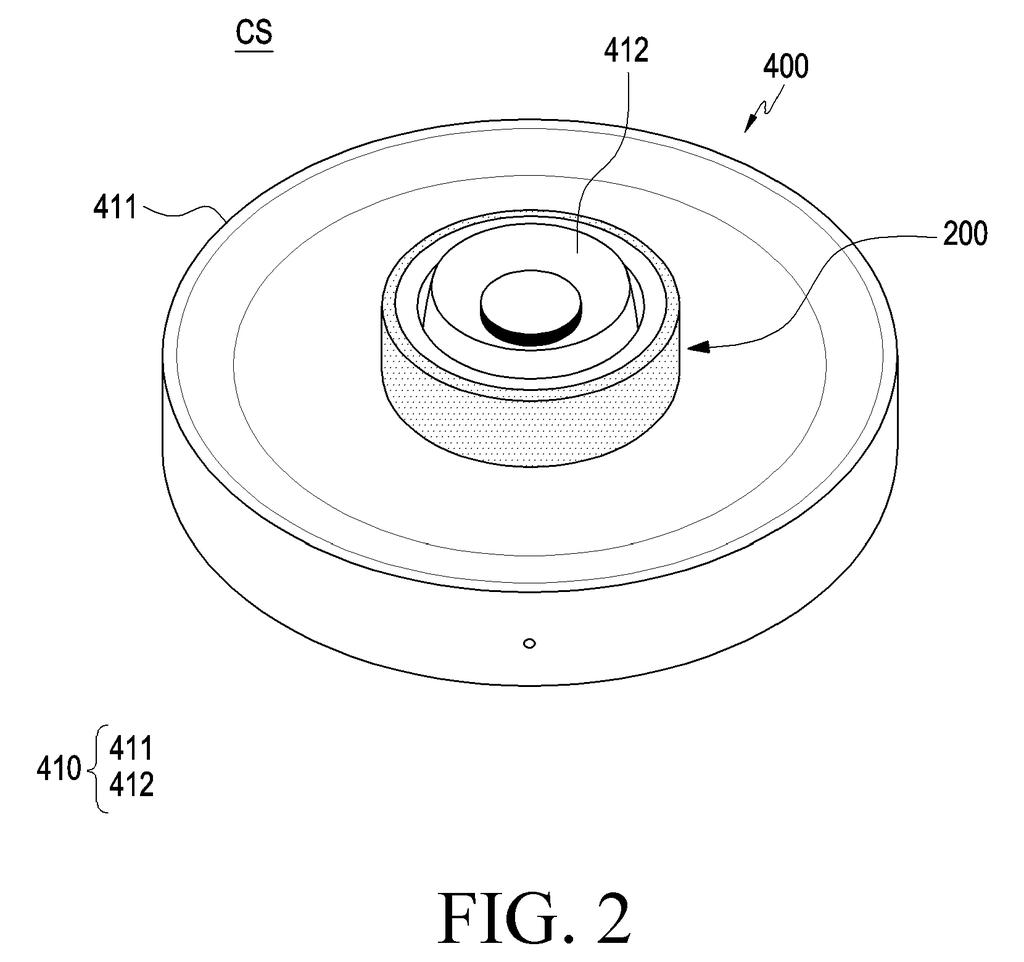
A smart ring rests on a circular charging dock to recharge wirelessly. Drawing from patent filing US 2026/0342132 A1.
A smart ring rests on a circular charging dock to recharge wirelessly.
See all 30 drawings from this filing ↓
Publication number US 2026/0342132 A1 US20260342132A1
Applicant Samsung Electronics Co., Ltd.
Filing date Apr 23, 2026
Publication date Oct 29, 2026
Inventors Taehyun WOO, Sangjoon MO, Chulhan KIM, Jedok KIM, Beomwoo GU
US classification 307/104
Status when we published Waiting for an examiner (Jun 16, 2026)
Parent application is a Continuation of PCTKR2026096038 (filed 2026-04-17)
Document 20 claims

What Samsung's flip-either-way ring charger does

You're half asleep at the end of the night, sliding your health-tracking ring onto its little charging post. You don't check which side is up. By morning, you'd like it to be full.

Samsung's filing describes a ring and cradle built so that works. The cradle is a small post you slide the ring over, with a groove that matches a bump on the inside of the ring. Both are symmetrical, so the ring fits either way up. Hidden in the cradle are two charging coils, one for each orientation, so one is always lined up with the ring's receiving coil.

Inside the ring, the parts are arranged like a clock face: a curved battery at the top, a charging coil at one end of it, a Bluetooth antenna at the other end, and the health sensors along the bottom.

From the filing · CLAIM 1
… a curved battery disposed inside the housing; a first wireless charging coil configured to wirelessly charge the curved battery via at least a portion of the inner housing …

Translation: The ring packs a curved battery and a charging coil that powers it from the inside.

How the ring packs a battery, coil and sensors

The ring has a metal outer shell and a plastic inner band that touches your finger. Inside, a curved battery fills the top. A charging coil (a loop of wire that receives power wirelessly) sits at one end of the battery, a Bluetooth antenna sits at the other end, and the health sensors sit in between, on the far side of the ring.

The filing spends a lot of effort on keeping the ring thin:

  • The coil sits on one side of a circuit board and the power-management parts sit on the other, so the whole stack is no thicker than the battery.
  • Because the inner band is curved, the coil has four wiring layers in the middle and a fifth near its edges. The extra metal cuts resistance and raises the coil's Q value (a score for how efficiently it passes power).
  • The inner band is thinner where the coil sits, so it gets closer to the charger.

The cradle is a base with a cylindrical post. A bump on the inside of the ring fits a groove in the post, and since both are symmetrical, the ring can go on either way up. A third coil in the cradle serves one orientation and a fourth serves the other. One variation puts a second coil in the ring too, so two coils charge at once.

From the filing · THE ABSTRACT
… at least one sensor configured to obtain data from a user and disposed at a third portion located between the first portion and the second portion.

Translation: Built in health sensors sit between the battery and antenna to track user data.

What a flip-proof ring charger means for you

If you wear a ring to track your sleep, heart rate and blood oxygen, charging is the chore that interrupts it. A cradle that accepts the ring either way up takes a little friction out of that routine. The layout is also aimed at keeping the ring thin, which matters when the thing lives on your finger all day.

The sensor described shines red and infrared light into your finger to read heart rate and blood oxygen. Nothing here changes what the ring measures. The filing lists blood sugar as a possible reading but gives no method for it. The value is in comfort and convenience: a smaller ring, a simpler nightly habit, and fewer mornings with a dead tracker.

That makes this Samsung's 44th filing we've tracked in our Battery & power coverage since May, adding to work like the robot charger-finding patent and the offline hub power explainer.

Editorial take

Nothing in this filing needs new science or new software. It is a layout of parts that anyone who follows wearables will recognize: a curved battery, a charging coil, a Bluetooth antenna and a light sensor. That puts it close to a shippable design, because the remaining work is manufacturing.

The hard part sits on the factory floor. The ring needs a housing with a thin plastic window where the coil sits, a circuit stack that fits under the battery's thickness, and a cradle with two precisely placed coils. Those are tooling and testing jobs, and they have to exist before anything ships.

The filing gives no battery life, charging speed or ring size, so the document can't say how this layout performs. The shortest route to a product is a ring and cradle designed together and sold as a pair.

Get our take in your Top Stories

Liked this breakdown? Add Patentlyze as a preferred source on Google, and our plain-English take shows up more often in your Top Stories the next time Samsung patent news breaks.

There are more where this came from

We read every patent application Big Tech publishes and send you the ones worth knowing. Plain English, free, every week.

The drawings

30 drawing sheets from US 2026/0342132 A1 · click any drawing to enlarge

Electronic parts that power the connected smart ring, drawing sheet 1 from US 2026/0342132 A1
Sheet 1 Electronic parts that power the connected smart ring
Dropping the ring onto its charging dock, drawing sheet 2 from US 2026/0342132 A1
Sheet 2 Dropping the ring onto its charging dock
How wireless power transfers from the dock to the ring, drawing sheet 3 from US 2026/0342132 A1
Sheet 3 How wireless power transfers from the dock to the ring
Controlling smart home gadgets and phones from your finger, drawing sheet 4 from US 2026/0342132 A1
Sheet 4 Controlling smart home gadgets and phones from your finger
Inner bumps that help orient the ring on its base, drawing sheet 5 from US 2026/0342132 A1
Sheet 5 Inner bumps that help orient the ring on its base
Symmetrical ridges line up the ring inside the charger, drawing sheet 6 from US 2026/0342132 A1
Sheet 6 Symmetrical ridges line up the ring inside the charger
Inside view of the battery, sensors, and charging coils, drawing sheet 7 from US 2026/0342132 A1
Sheet 7 Inside view of the battery, sensors, and charging coils
Curved battery and health sensors packed inside the ring frame, drawing sheet 8 from US 2026/0342132 A1
Sheet 8 Curved battery and health sensors packed inside the ring frame
Show the other 22 sheets
Two ways to stack the charging coil and internal circuitry, drawing sheet 9 from US 2026/0342132 A1
Sheet 9 Two ways to stack the charging coil and internal circuitry
Positioning the charging coil beneath a thin inner window, drawing sheet 10 from US 2026/0342132 A1
Sheet 10 Positioning the charging coil beneath a thin inner window
Letting the coil face out through an open inner rim, drawing sheet 11 from US 2026/0342132 A1
Sheet 11 Letting the coil face out through an open inner rim
Coiling the antenna wire alongside the ring battery, drawing sheet 12 from US 2026/0342132 A1
Sheet 12 Coiling the antenna wire alongside the ring battery
Connecting internal coil tracks using vertical bridges, drawing sheet 13 from US 2026/0342132 A1
Sheet 13 Connecting internal coil tracks using vertical bridges
Stacking multiple wiring layers to fit inside the curved frame, drawing sheet 14 from US 2026/0342132 A1
Sheet 14 Stacking multiple wiring layers to fit inside the curved frame
Placing contact points at the corners of the antenna, drawing sheet 15 from US 2026/0342132 A1
Sheet 15 Placing contact points at the corners of the antenna
Routing outer wiring directly into deeper antenna layers, drawing sheet 16 from US 2026/0342132 A1
Sheet 16 Routing outer wiring directly into deeper antenna layers
Inside layout of the battery, sensors, and circuitry, drawing sheet 17 from US 2026/0342132 A1
Sheet 17 Inside layout of the battery, sensors, and circuitry
Dropping the ring right side up onto the dock, drawing sheet 18 from US 2026/0342132 A1
Sheet 18 Dropping the ring right side up onto the dock
Top view showing the coils align in normal orientation, drawing sheet 19 from US 2026/0342132 A1
Sheet 19 Top view showing the coils align in normal orientation
Placing the ring upside down onto the same charger, drawing sheet 20 from US 2026/0342132 A1
Sheet 20 Placing the ring upside down onto the same charger
Flipped ring aligns with the opposite charging coil, drawing sheet 21 from US 2026/0342132 A1
Sheet 21 Flipped ring aligns with the opposite charging coil
Charging coils set inside the dock wall, drawing sheet 22 from US 2026/0342132 A1
Sheet 22 Charging coils set inside the dock wall
Window inserts placed over the dock charging coils, drawing sheet 23 from US 2026/0342132 A1
Sheet 23 Window inserts placed over the dock charging coils
Magnetic charging parts protruding through the dock frame, drawing sheet 24 from US 2026/0342132 A1
Sheet 24 Magnetic charging parts protruding through the dock frame
Circuit parts that send power through two separate charger coils, drawing sheet 25 from US 2026/0342132 A1
Sheet 25 Circuit parts that send power through two separate charger coils
How the ring fits a charging coil along its battery, drawing sheet 26 from US 2026/0342132 A1
Sheet 26 How the ring fits a charging coil along its battery
Placing the wireless power coil next to the sensors, drawing sheet 27 from US 2026/0342132 A1
Sheet 27 Placing the wireless power coil next to the sensors
Charger dock that powers the ring in any position, drawing sheet 28 from US 2026/0342132 A1
Sheet 28 Charger dock that powers the ring in any position
How the multi-coil dock charges a ring with bottom-mounted coils, drawing sheet 29 from US 2026/0342132 A1
Sheet 29 How the multi-coil dock charges a ring with bottom-mounted coils
Power circuits directing charge across four dock transmitters, drawing sheet 30 from US 2026/0342132 A1
Sheet 30 Power circuits directing charge across four dock transmitters
Browse all the drawings 30 drawing sheets
Patent filing page

Source. Full patent text and figures from the official USPTO publication PDF.
Reader comments

Be the first to weigh in

Start the discussion

Real name or a handle, either is fine. Comments are read by a person before they appear, so allow a little time. Keep it about the filing.