
Samsung Patents a Removable Gear to Free a Broken Rolling Projector
Samsung's patent for a rolling projector tackles an ordinary problem: what happens when the motor that aims the lens breaks and the gears refuse to budge?
What Samsung's removable projector gear does
A little projector on wheels rolls across your living room, tips its lens up toward the ceiling, and then its tilt motor dies. The lens is stuck pointing at the ceiling, and pushing it back down by hand does nothing.
The culprit is a worm gear, a screw-like gear that turns a wheel. It holds its position so firmly that force applied from the other end cannot turn it backward. That is useful while the motor works and a trap once it fails.
Samsung's answer is a gear you can take out. The gear linking the motor to the moving part is held on by one screw, reachable through a hole in the outer frame. Remove the screw, slide the gear out, and the top half swings freely, so you or someone doing a repair can move it by hand.
… a first gear detachably coupled to the rotating shaft and rotatable by power from the motor transmitted through the rotating shaft; and a second gear configured to engage with the first gear such that the rotating frame rotates relative to the fixed frame …
Translation: A removable gear system connects the motor to the rotating frame.
How the gear comes out through the frame hole
The patent covers a motorized pivot with an escape hatch. The device has a fixed frame that stays put and a rotating frame that carries the projection lens, so the image can be aimed at a wall, floor or ceiling. A motor drives the turn through a worm gear (a screw-shaped gear that spins a wheel and holds its position very firmly) and a rotating shaft.
At the end of the shaft sits the first gear, a spur gear (flat teeth parallel to the shaft). It is mounted on a flat-sided section of the shaft, called a D-cut, and held with a screw. Its teeth mesh with a second gear fixed to the outer frame. When the motor turns the first gear, it travels along the second gear and swings the rotating frame around a central bearing.
The twist is the removal. The outer frame has a through-hole wider than the first gear. Take out the screw through that hole, slide the gear off the shaft along the direction of its teeth, and the two gears no longer touch. With the self-locking worm gear out of the chain, the frame can be turned by external force.
The filing also describes:
- A pair of rotating frames joined by a base, with the motor driving only one side.
- A base cover that dampens motor vibration.
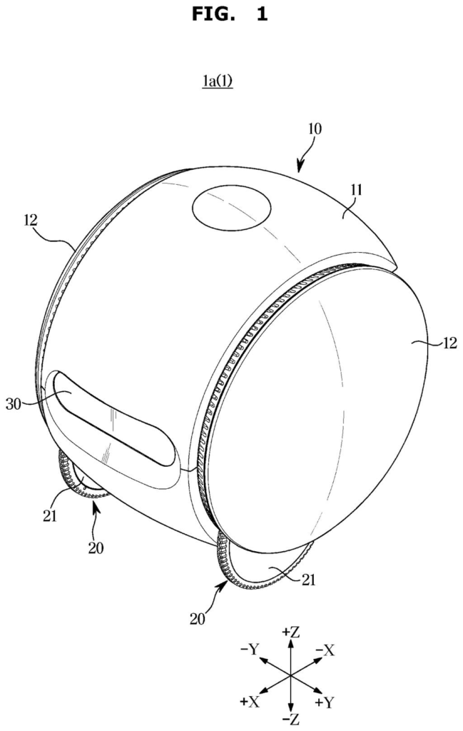
- A wheeled projector with an obstacle-detecting sensor as the example device.
The rotating frame is rotatable relative to the fixed frame by external force when the first gear and the second gear are separated.
Translation: You can turn the device by hand once the gears are disconnected.
What this means for wheeled home projectors
If projectors that roll around your home become common, they will have motors that aim the lens, and motors fail. A design like this means a stuck lens does not have to mean a dead product. Someone could free the moving part, and the filing says this works without pulling the fixed and rotating frames apart.
It also shows an engineering tradeoff. Samsung wants the strong holding power of a worm gear, which keeps the lens steady and transmits power efficiently, without paying for it when something breaks. For you, that could mean easier repairs and fewer units written off over one failed part.
Samsung's 86th filing in the camera patents we cover since May follows work like stopping multi-camera data loss and keeping magnets from neighboring lenses, which we've tracked across 86 applications.
A projector that can tilt and swivel is useful until its motor fails, and then the lens stays wherever it last pointed. Getting it to move again, even just enough to pack it up or aim it somewhere sensible, normally means dismantling the whole unit. That is a real cost: a stuck projector is functionally broken even if most of its parts work fine, and repair shops charge accordingly for access that should be simple.
The fix here is mechanical and direct. One gear slides out of contact so the frame turns freely by hand, then slides back in so the motor holds its position during normal use.
For a moving part that sees years of daily adjustment, the ability to override the motor without tools or software is exactly what separates a repairable product from a disposable one. The problem is common enough, and the approach small enough, that the match between the two feels right.
Get our take in your Top Stories
Liked this breakdown? Add Patentlyze as a preferred source on Google, and our plain-English take shows up more often in your Top Stories the next time Samsung patent news breaks.
There are more where this came from
We read every patent application Big Tech publishes and send you the ones worth knowing. Plain English, free, every week.
The drawings
11 drawing sheets from US 2026/0349320 A1 · click any drawing to enlarge


Show the other 3 sheets


Want this weekly breakdown for a company we don't cover? Patentlyze Pro →
Be the first to weigh in