
Apple Files Patent to Brighten Headset Displays With Two Overlapping Patterns in the Lens
Apple's filing tucks two light-steering patterns into one lens, then dials each one up or down depending on whether that spot sits near your brow or your cheek.
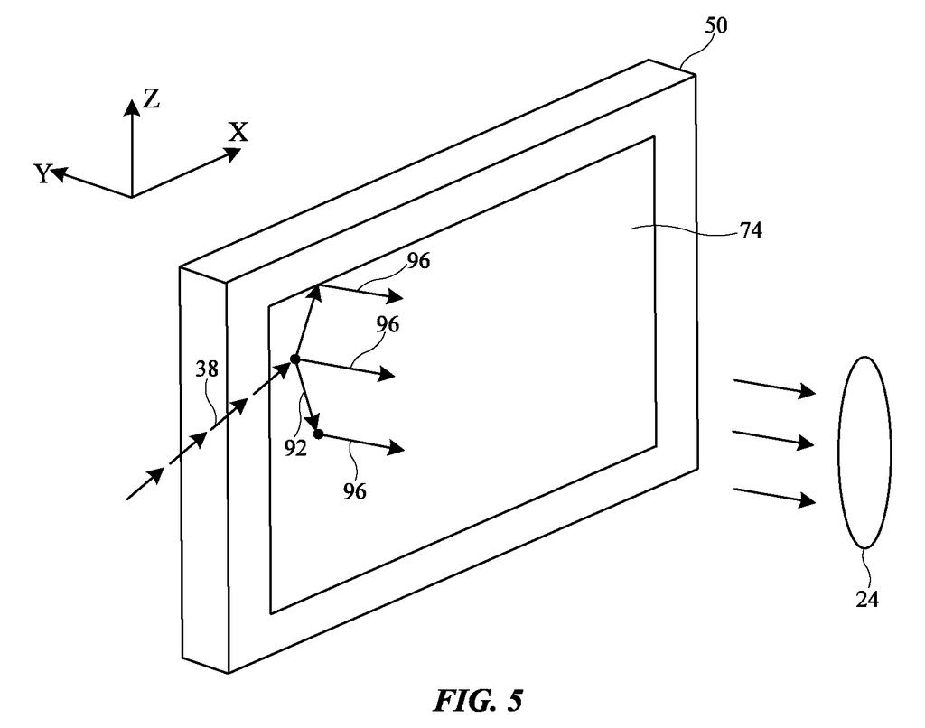
What Apple's two-pattern headset lens does
Every time you slip on a pair of AR glasses, a thin sheet of glass has to spread a tiny projected image across your whole view. The light enters near your nose or temple, bounces along the lens, and has to come out toward your eye evenly. If it doesn't, part of the picture looks dim.
Apple's filing describes two overlapping patterns etched into that lens. Each one stretches the light up or down and sends it out toward your eye, so two patterns do the work that would otherwise take four separate ones.
The twist is that each pattern gets stronger only where it's needed. One is strongest near your brow, the other near your cheek, and both fade smoothly toward the opposite edge. The goal is a brighter, more even image without making the lens thicker.
a first diffractive grating that diffracts the light out of the waveguide, and a second diffractive grating that at least partially overlaps the first diffractive grating, that is non-parallel to the first diffractive grating, and that diffracts the light out of the waveguide …
Translation: Two crossed microscopic patterns work together to steer the image beam out of the glass and toward your eyes.
How the brow and cheek patterns trade off
The patent describes a display built around a waveguide, a clear plate that carries light along its length by bouncing it between its surfaces (called total internal reflection). An input coupler sends image light from a display module into the plate.
In the eye-facing area, a surface relief grating structure takes over. That means microscopic ridges and grooves formed in a layer on the plate. It has at least two overlapping gratings that point in different directions. One spreads the light upward and the other spreads it downward. Each also sends the light spread by the other grating out of the plate toward the eye box (the spot where your eye sits).
The claims center on modulating (varying) each grating's strength across the lens. In the main example, one grating is strongest at the brow edge and fades in a straight line to nothing at the cheek edge, while the other does the opposite. The reasoning is that most light needing the first grating's help lands on the upper half, and most light needing the second's lands on the lower half.
The filing also describes raising diffraction efficiency (how much light gets pulled out) moving away from the input edge, so the light doesn't all escape before reaching the far side. Other variations include curved or stepped fade patterns, a third grating to catch light that reflects backward, and leaving gratings out of some areas to cut rainbow glints and keep ceiling lights from bouncing into the eye.
Modulation functions may be used to vary the grating strengths of the SRGs in the SRG structure between brow and cheek regions of the SRG structure.
Translation: The microscopic patterns change intensity from top to bottom so the picture looks equally bright across your face.
Why this matters for thinner AR glasses
If you wear a headset or glasses with a see-through display, brightness and picture evenness are what you notice first. Squeezing more of the projector's light to your eye means a brighter image for the same battery drain, or the same image from a smaller light source.
The filing itself says that using two gratings for four jobs can cut manufacturing cost and complexity, shorten the light's travel distance, and save space without shrinking the field of view. That matters for glasses that need to stay thin and light. It's a lens-design refinement, so you'd see it as a better picture rather than a new feature.
That makes this Apple's 115th filing we've tracked in our AR glasses watchlist since May, following patents like eye tracking via the lens and one on poor fit alerts.
Every trick in this design costs something. Fading each pattern out where it matters least saves light, yet it leaves the middle band, where both patterns overlap, to carry the work of keeping the image even.
The filing flags a second cost itself. Trimming the overlap near the edges helps hide rainbow glints and keeps ceiling lights from bouncing into your eye, but trimming too much shrinks the zone where your eye can sit and still see a clean picture. Patterns that change shape continuously across a lens are also harder to make precisely than a uniform one.
Verdict: those costs look small next to the gain. One lens doing four jobs is a sound trade for glasses that must stay thin and light, and the brow-to-cheek tuning refines how waveguide lenses already work.
Get our take in your Top Stories
Liked this breakdown? Add Patentlyze as a preferred source on Google, and our plain-English take shows up more often in your Top Stories the next time Apple patent news breaks.
There are more where this came from
We read every patent application Big Tech publishes and send you the ones worth knowing. Plain English, free, every week.
The drawings
9 drawing sheets from US 2026/0339035 A1 · click any drawing to enlarge


Show the other 1 sheets

Want this weekly breakdown for a company we don't cover? Patentlyze Pro →
Be the first to weigh in