
Apple · Filed Jul 13, 2026 · Published Nov 12, 2026

Apple Files Patent for a Phone Screen Whose Camera Holes Respond to Taps and Swipes

Apple describes a phone screen where the holes for the camera and face-unlock sensors are not dead zones: you could tap or swipe right over them. A small strip of screen between the holes could also light up when a notification arrives.
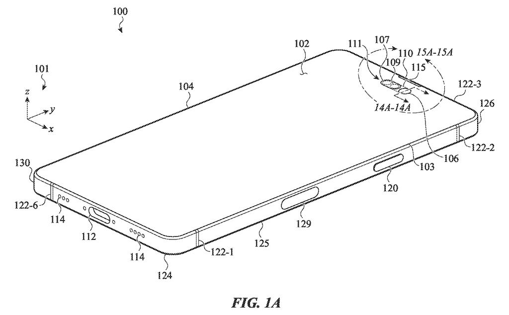
A smartphone display with cutouts near the top edge designed to integrate front cameras and sensors directly into the screen. Drawing from patent filing US 2026/0361815 A1.
A smartphone display with cutouts near the top edge designed to integrate front cameras and sensors directly into the screen.
See all 59 drawings from this filing ↓
Publication number US 2026/0361815 A1 US20260361815A1
Applicant Apple Inc.
Filing date Jul 13, 2026
Publication date Nov 12, 2026
Inventors Matthew D. Hill, Rasamy Phouthavong, Jun Sik Ham, James A. Bertin, Benjamin J. Kallman, Sherry Cao
US classification 455/566
Status when we published Waiting for an examiner (Aug 3, 2026)
Parent application is a Continuation of 17903864 (filed 2022-09-06)
Document 20 claims

What Apple's touchable camera cutout does

Ever tapped your phone's screen and noticed that the camera cutout at the top just sits there doing nothing? In this Apple patent application, that spot gets a job.

The screen has two small holes, one for the front camera and one for the face-unlock sensors. Between them is a thin strip of display that can show icons, shapes or a light to signal a notification. The touch system also keeps working over the holes, even right above the lenses.

So a swipe across the cutout, or a tap on one sensor instead of the other, could trigger different actions. When nothing is happening, the strip can stay dark or show a plain graphic, so the two holes can look like one continuous patch of screen.

From the filing · CLAIM 1
… a display positioned below the front cover, the display defining: an active display region; a first hole surrounded by the active display region; and a second hole surrounded by the active display region; …

Translation: The screen has cutouts for sensors that are completely enclosed by the normal viewing area.

How the touch layer reads taps over lenses

The filing describes a phone whose front glass sits over a display with two small holes cut through the active screen area. An optical sensor sits under each hole. The description names a front camera, an infrared light projector and an infrared image sensor used for face recognition.

The main twist is in the touch layer (the thin grid of electrodes that senses your finger). It is set up to detect touches in two places:

  • The normal active part of the screen
  • The glass directly over a hole, including right above a sensor or a light emitter

Another claim treats the sensor area as a graphically inactive region (a spot that cannot draw pictures) that still accepts input, including gestures such as a swipe. Touching over the first sensor can trigger one action, and touching over the second can trigger a different one. A dark opaque mask (a printed layer that hides the parts behind the glass) has openings over the holes, and it may sit on a textured polymer coating.

A third claim covers the strip of display between the two holes. It can show its own graphic when a notification arrives. Before that, it may show nothing or a different graphic.

From the filing · THE ABSTRACT
… a touch-sensing component configured to detect a first touch input applied to the front cover in the active display region of the display and a second touch input applied to the front cover over the first hole in the display.

Translation: Touch sensors can register gestures made both on the main screen and directly over the camera cutouts.

What this means for the top of your screen

For you, this could mean the top of your phone's screen does more. A glow between the camera and face-unlock sensors could signal an incoming message, and a swipe across that spot could work as a shortcut. The claims leave the actual shortcuts open and only say that two different touches can trigger two different actions.

Camera holes in a screen are hard to avoid, so this filing treats them as part of the interface rather than a blemish. The description also says the same idea could apply to other devices, such as watches and tablets, though the claims focus on phones.

Apple's 54th filing in our cell phone coverage since May joins earlier applications like one on scratch-resistant curved glass and one on activity-based location collection in the set we've tracked.

Editorial take

The part the claims cover is small and buildable: a touch layer that keeps working over the camera holes, plus a thin strip of screen between them. The phone in the description already has a screen with holes and sensors underneath. What is added is asking the touch system to read fingers over glass that cannot draw pictures.

The route to a product looks short. It takes a touch layer that covers the hole areas, plus software that decides what a tap on one sensor or a swipe across the strip does. The claims only say the two actions differ, so the useful part is still undecided.

The hard parts are habit and smudges. Fingerprints on a camera lens are an obvious worry for anything people touch, and a tap target that small has to be easy to hit. Whether people want to touch their camera is a design question, and software can answer it long after the hardware is locked.

Get our take in your Top Stories

Liked this breakdown? Add Patentlyze as a preferred source on Google, and our plain-English take shows up more often in your Top Stories the next time Apple patent news breaks.

There are more where this came from

We read every patent application Big Tech publishes and send you the ones worth knowing. Plain English, free, every week.

The drawings

59 drawing sheets from US 2026/0361815 A1 · click any drawing to enlarge

Front view of the phone showing touch-sensitive camera cutouts, drawing sheet 1 from US 2026/0361815 A1
Sheet 1 Front view of the phone showing touch-sensitive camera cutouts
Back of the phone showing three rear cameras and flash, drawing sheet 2 from US 2026/0361815 A1
Sheet 2 Back of the phone showing three rear cameras and flash
Another phone design with a top-edge sensor notch, drawing sheet 3 from US 2026/0361815 A1
Sheet 3 Another phone design with a top-edge sensor notch
Rear view of the second design with dual camera lenses, drawing sheet 4 from US 2026/0361815 A1
Sheet 4 Rear view of the second design with dual camera lenses
Internal parts of the three-camera phone model, drawing sheet 5 from US 2026/0361815 A1
Sheet 5 Internal parts of the three-camera phone model
Exploded view of the dual-camera phone model, drawing sheet 6 from US 2026/0361815 A1
Sheet 6 Exploded view of the dual-camera phone model
Main structural frame separating the screen and rear glass, drawing sheet 7 from US 2026/0361815 A1
Sheet 7 Main structural frame separating the screen and rear glass
Metal midframe chassis showing cutouts for the battery pack, drawing sheet 8 from US 2026/0361815 A1
Sheet 8 Metal midframe chassis showing cutouts for the battery pack
Show the other 51 sheets
Layers inside the phone that cushion and ground internal parts, drawing sheet 9 from US 2026/0361815 A1
Sheet 9 Layers inside the phone that cushion and ground internal parts
An L-shaped circuit board designed to fit around internal parts, drawing sheet 10 from US 2026/0361815 A1
Sheet 10 An L-shaped circuit board designed to fit around internal parts
The underside of the main board showing mounted computer chips, drawing sheet 11 from US 2026/0361815 A1
Sheet 11 The underside of the main board showing mounted computer chips
Where the main circuit board sits beneath the back panel, drawing sheet 12 from US 2026/0361815 A1
Sheet 12 Where the main circuit board sits beneath the back panel
Cutaway views showing how the battery rests against internal supports, drawing sheet 13 from US 2026/0361815 A1
Sheet 13 Cutaway views showing how the battery rests against internal supports
A protective frame holding the battery inside the phone, drawing sheet 14 from US 2026/0361815 A1
Sheet 14 A protective frame holding the battery inside the phone
Built-in clips and coils lining the phone's rear cover, drawing sheet 15 from US 2026/0361815 A1
Sheet 15 Built-in clips and coils lining the phone's rear cover
Spring-loaded fasteners that lock internal frame pieces in place, drawing sheet 16 from US 2026/0361815 A1
Sheet 16 Spring-loaded fasteners that lock internal frame pieces in place
Spring clips inside the corner that brace the rear cameras, drawing sheet 17 from US 2026/0361815 A1
Sheet 17 Spring clips inside the corner that brace the rear cameras
Brackets locking the rear camera lenses firmly in place, drawing sheet 18 from US 2026/0361815 A1
Sheet 18 Brackets locking the rear camera lenses firmly in place
A water seal placed between two adjacent camera rings, drawing sheet 19 from US 2026/0361815 A1
Sheet 19 A water seal placed between two adjacent camera rings
Protective metal trim surrounding the rear camera lens, drawing sheet 20 from US 2026/0361815 A1
Sheet 20 Protective metal trim surrounding the rear camera lens
Hollowed trim rings designed to absorb lens impacts, drawing sheet 21 from US 2026/0361815 A1
Sheet 21 Hollowed trim rings designed to absorb lens impacts
Alternative waterproof seals securing the outer camera trim, drawing sheet 22 from US 2026/0361815 A1
Sheet 22 Alternative waterproof seals securing the outer camera trim
Double-layered protective rims around the camera glass, drawing sheet 23 from US 2026/0361815 A1
Sheet 23 Double-layered protective rims around the camera glass
Sloped outer trim helping deflect side hits to the lens, drawing sheet 24 from US 2026/0361815 A1
Sheet 24 Sloped outer trim helping deflect side hits to the lens
Internal springs holding the rear camera tightly in place, drawing sheet 25 from US 2026/0361815 A1
Sheet 25 Internal springs holding the rear camera tightly in place
Front sensor holes positioned near the top speaker notch, drawing sheet 26 from US 2026/0361815 A1
Sheet 26 Front sensor holes positioned near the top speaker notch
Angled proximity sensor layout behind the front screen, drawing sheet 27 from US 2026/0361815 A1
Sheet 27 Angled proximity sensor layout behind the front screen
Stacked screen and camera parts lining up with front cutouts, drawing sheet 28 from US 2026/0361815 A1
Sheet 28 Stacked screen and camera parts lining up with front cutouts
Light blocking masks placed between the screen layers and lenses, drawing sheet 29 from US 2026/0361815 A1
Sheet 29 Light blocking masks placed between the screen layers and lenses
Diffusers and coatings that conceal internal sensors through glass, drawing sheet 30 from US 2026/0361815 A1
Sheet 30 Diffusers and coatings that conceal internal sensors through glass
Touch sensing rings wrapping around each front camera cutout, drawing sheet 31 from US 2026/0361815 A1
Sheet 31 Touch sensing rings wrapping around each front camera cutout
Grid and border patterns for detecting finger taps around cutouts, drawing sheet 32 from US 2026/0361815 A1
Sheet 32 Grid and border patterns for detecting finger taps around cutouts
Stacking touch layers under the glass around the camera window, drawing sheet 33 from US 2026/0361815 A1
Sheet 33 Stacking touch layers under the glass around the camera window
Close-up views of the border sealing the camera opening, drawing sheet 34 from US 2026/0361815 A1
Sheet 34 Close-up views of the border sealing the camera opening
Tapered screen edges that leave clear space for sensors, drawing sheet 35 from US 2026/0361815 A1
Sheet 35 Tapered screen edges that leave clear space for sensors
Tapping different sensor cutouts to trigger on-screen actions, drawing sheet 36 from US 2026/0361815 A1
Sheet 36 Tapping different sensor cutouts to trigger on-screen actions
Swiping across the camera cutout to reveal notifications, drawing sheet 37 from US 2026/0361815 A1
Sheet 37 Swiping across the camera cutout to reveal notifications
Mounting front camera lenses directly beneath the screen glass, drawing sheet 38 from US 2026/0361815 A1
Sheet 38 Mounting front camera lenses directly beneath the screen glass
Seals that block dust from the front camera lens, drawing sheet 39 from US 2026/0361815 A1
Sheet 39 Seals that block dust from the front camera lens
Speaker vents hidden along the phone's top rim, drawing sheet 40 from US 2026/0361815 A1
Sheet 40 Speaker vents hidden along the phone's top rim
Ear speaker port placed beside the front glass, drawing sheet 41 from US 2026/0361815 A1
Sheet 41 Ear speaker port placed beside the front glass
Protective mesh that blocks dust from the speaker, drawing sheet 42 from US 2026/0361815 A1
Sheet 42 Protective mesh that blocks dust from the speaker
How the flash adjusts light for wider scenes, drawing sheet 43 from US 2026/0361815 A1
Sheet 43 How the flash adjusts light for wider scenes
Cross sections of the camera flash lens and light emitter, drawing sheet 44 from US 2026/0361815 A1
Sheet 44 Cross sections of the camera flash lens and light emitter
Lighting only the center to create a narrow spotlight, drawing sheet 45 from US 2026/0361815 A1
Sheet 45 Lighting only the center to create a narrow spotlight
Activating mid-ring emitters to widen the camera flash beam, drawing sheet 46 from US 2026/0361815 A1
Sheet 46 Activating mid-ring emitters to widen the camera flash beam
Powering corner emitters to cast the widest flash beam, drawing sheet 47 from US 2026/0361815 A1
Sheet 47 Powering corner emitters to cast the widest flash beam
Ridges on the flash window that spread light evenly, drawing sheet 48 from US 2026/0361815 A1
Sheet 48 Ridges on the flash window that spread light evenly
Parts of the motor that creates phone vibrations, drawing sheet 49 from US 2026/0361815 A1
Sheet 49 Parts of the motor that creates phone vibrations
Inside view of the vibration motor showing its suspension springs, drawing sheet 50 from US 2026/0361815 A1
Sheet 50 Inside view of the vibration motor showing its suspension springs
Side button unit that fits into the phone frame, drawing sheet 51 from US 2026/0361815 A1
Sheet 51 Side button unit that fits into the phone frame
Contact pads and switches inside the side button assembly, drawing sheet 52 from US 2026/0361815 A1
Sheet 52 Contact pads and switches inside the side button assembly
Angled sensor bracket mounting to the device wall, drawing sheet 53 from US 2026/0361815 A1
Sheet 53 Angled sensor bracket mounting to the device wall
Glass screen cover lifting away from the phone body, drawing sheet 54 from US 2026/0361815 A1
Sheet 54 Glass screen cover lifting away from the phone body
Cross sections of optical coatings over the camera area, drawing sheet 55 from US 2026/0361815 A1
Sheet 55 Cross sections of optical coatings over the camera area
Protective shield fitting over the main circuit board, drawing sheet 56 from US 2026/0361815 A1
Sheet 56 Protective shield fitting over the main circuit board
Shielding cans that protect internal chips from interference, drawing sheet 57 from US 2026/0361815 A1
Sheet 57 Shielding cans that protect internal chips from interference
Contoured shielding layers that fit closely over circuit boards, drawing sheet 58 from US 2026/0361815 A1
Sheet 58 Contoured shielding layers that fit closely over circuit boards
Key hardware components inside the phone linked together, drawing sheet 59 from US 2026/0361815 A1
Sheet 59 Key hardware components inside the phone linked together
Browse all the drawings 59 drawing sheets
Patent filing page

Source. Full patent text and figures from the official USPTO publication PDF.
Reader comments

Be the first to weigh in

Start the discussion

Real name or a handle, either is fine. Comments are read by a person before they appear, so allow a little time. Keep it about the filing.