
Apple
Apple · Battery & power · Filed May 12, 2026 · USPTO published Nov 12, 2026 · This week's release
Apple Files Patent for a Wireless Charger Puck Built From Fewer Parts
The little cover you snap your watch onto might soon do two jobs. Apple's patent mixes carbon into the plastic so it doubles as the shield that used to be a separate part.
- Publication number
- US 2026/0361143 A1(US20260361143A1)
- Applicant
- Apple Inc.
- Filed · Published
- May 12, 2026 · Nov 12, 2026
- Inventors
- James C. Wu, Vi Phan, Rajesh Saliya, Grant S. Haug, Jun-Ya Fong, Dao Kai Lim
- Status when we published
- Waiting for an examiner
- Document
- 20 claims
- US classification
- 320/108
- Parent application
- Claims priority from a provisional application 63804561 (filed May 12, 2025)
What Apple's one-piece charging puck cap does
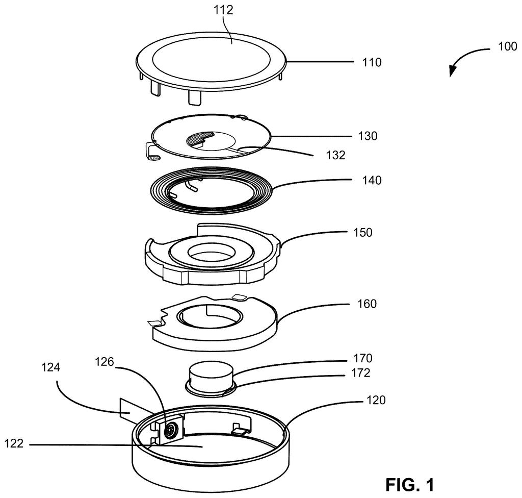
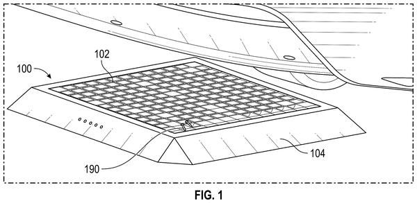
Ever wondered what's inside the little disc you snap your watch or earbuds onto? More than you'd think: a magnet, a coil of wire, a shield that keeps stray electrical signals in check, and the cover you actually touch. Apple's patent folds the shield into the cover.
The trick is to mix a little carbon (or silver) into the plastic cover so the plastic itself conducts just enough electricity to do the shield's job. Fewer parts means a simpler build and less to assemble. It also removes one layer between the charger's coil and your device, and a shorter gap helps charging work better.
There's a catch: carbon plastic is black. So the filing also describes a cover with a colored layer on top and a hidden conductive layer underneath, or a thin conductive coating applied to the underside of a regular plastic cover.
a top cap to engage with an electronic device when the electronic device is charged by the charging device, wherein the top cap comprises a first material doped with a second conducive material, wherein the second conducive material provides conductivity to the top cap.
Translation: The charging surface is made of a base material mixed with something conductive to carry electricity.
How carbon-doped plastic doubles as a shield
A charging puck normally stacks several parts: a cover you touch, a separate e-shield (a thin conductive layer that blocks stray electric fields and interference from the charging coil), the coil, a magnetic backing, and a magnet. Apple's claims put the shield's job into the cover, called a top cap.
The claims describe three versions:
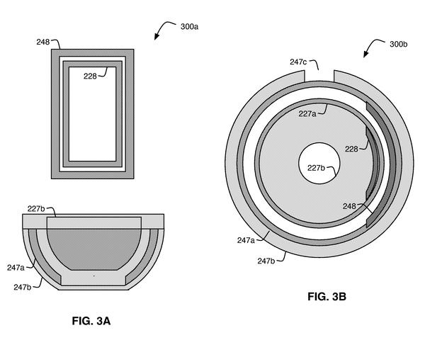
- A top cap of resin or plastic doped (mixed) with a conductive material such as carbon or silver.
- A two-layer cap, one layer of ordinary material and one doped with a conductive material. The filing describes making it by two-shot molding (molding one layer, then a second).
- A cap with a conductive coating on its underside, applied by pad printing, 3D printing, jet spraying, or vapor deposition.
The tricky part is eddy currents, swirling currents that form in a conductive layer near the coil and waste power meant for your device. So the conductivity has to stay limited. The description gives a sheet resistance of about 100 to 1,000 ohms per square (how strongly a thin layer resists current). Other fixes include slots in the shield or several thin conductive layers separated by insulation.
Conductive glue links the layer to the puck's housing, which acts as electrical ground. Dependent claims say nothing sits between the coil and the cap.
… a contacting surface and an e-shield can be combined into a single top cap structure.
Translation: Apple combined the outside contact pad and the electromagnetic shield into one part to save space.
Why a thinner charging puck stack matters
For you, the likely payoff is a simpler charger and a slightly better charge. Every part removed from a puck is one less thing to mold, stack, and glue in a factory. The description also says closing the gap between the charging coil and your device can improve charging efficiency. Thinner molded layers, which the filing says a low-pressure molding process allows, push the same way.
The filing also cares about looks and heat. Carbon turns plastic black, so the two-layer version lets the visible surface come in other colors. A heat-conducting plastic can help pull warmth out of your device while it charges. The filing lists watches, rings, earbuds, headphones, phones, laptops, and tablets as devices the puck could charge.
Apple's 26th filing we've tracked in battery and power since May follows separate earbud charging spots and detecting metal near wireless chargers.
Source: US 2026/0361143 A1 at the USPTO (PDF). Full patent text and figures are in the official publication.
Get our take in your Top Stories
Liked this breakdown? Add Patentlyze as a preferred source on Google, and our plain-English take shows up more often in your Top Stories the next time Apple patent news breaks.
Add Patentlyze on Google
One click.
There are more where this came from
We read every patent application Big Tech publishes and send you the ones worth knowing. Plain English, free, every week.
The drawings · 10 sheets
10 drawing sheets from US 2026/0361143 A1 · click any drawing to enlarge


Show the other 2 sheets


More from Apple
All 672 Apple patents →

More in Battery & power
All 116 Battery & power patents →
Samsung
Samsung Patents a Wireless Charger That Spots Metal Objects Before Fast Charging Starts
Tesla
Tesla Patents a Wireless Charger That Ignores Temperature and Finds Real Metal

Samsung
Samsung Patents a Wireless Charger That Negotiates Voltage on Both Ends
Samsung
No comments yet