
Apple Files Patent for a Headset That Senses When Its Own Frame Bends
Apple's headset has two eyepieces joined by a part that bends, so the device needs a way to know when they drift out of line. This filing answers with small light sensors that watch the gap.
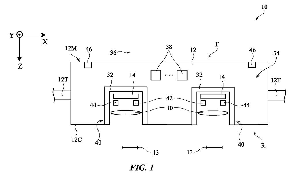
Why Apple's bendable headset must check itself
You pull a headset over your head and the frame flexes a little to fit your face. The left and right eyepieces shift a hair out of place, and the 3D picture in front of you only looks right when those two eyepieces stay lined up.
Apple's filing describes a headset where the two eyepieces are joined by a bendable bridge, so they can move against each other. To track that movement, it puts tiny lights on one eyepiece and light sensors on the other. A sensor with a perforated cover reads the shadow patterns the light makes, and the headset works out how far and in which direction the eyepieces moved.
The filing also describes a laser version that can pick up shifts smaller than a thousandth of a millimeter.
… a flexible portion that, when flexed, allows the first and second optical modules to move with respect to each other …
Translation: A bendable frame part lets the two display screens shift slightly when the headset flexes.
How light patterns reveal a twisting headset
The headset has two optical modules (the left and right eyepiece units, each with its own display and lens) joined by a support structure with a flexible section. When that section twists or bends, the modules move relative to each other. The filing calls that a relative pose displacement, meaning how far and in which way one module has shifted or tilted compared with the other. It describes three ways to measure it.
- Shadow patterns (claim 1): An emitter on one module sends out diffused light (soft, spread-out light). On the other module, an image sensor sits behind a patterned mask, an opaque sheet with an array of small openings. The light passing through casts a diffraction pattern (a shadow pattern) on the sensor. Sideways movement shifts the pattern, and a change in distance changes its size. Several LEDs can take turns, and software compares each reading with a pattern recorded at calibration.
- Laser interference (claim 14): A laser beam is split in two. One beam bounces off a fixed mirror and the other off a half mirror on the second module. The two returning beams overlap and create an interference pattern (stripes formed when light waves reinforce or cancel each other), which reveals movement in position. A second detector tracks where a beam spot lands, which reveals rotation.
- Two lasers and a rigid bar (claim 21): Each module aims a laser at an angle detector mounted on a rigid bar that does not flex. Where each spot lands shows how each module has rotated.
The filing says the laser approach can resolve movement below one micron.
… control circuitry configured to analyze the one or more diffraction patterns sensed by the image sensor of the detector to determine a relative pose displacement between the first and second optical modules …
Translation: Built-in chips process light patterns to precisely measure how far the screens have moved apart.
How far this sensor idea is from a real headset
Headsets with a rigid frame can be lined up once at the factory, the filing says. A headset with a bendable bridge cannot, because the alignment changes while you wear it. This filing gives a flexible design a way to measure that change continuously, so the left and right images can be adjusted to stay matched as the frame flexes.
The details point to a layered approach. Cheap LEDs and a small image sensor handle everyday readings, and lasers add much finer precision. The filing also describes combining several sensor pairs to cover all six ways two parts can move: three directions and three rotations. For mixed reality, where virtual objects have to sit convincingly in your actual room, keeping the two views aligned matters a lot.
That makes this Apple's 108th filing we've tracked on our AR glasses watch since May, a series that includes a pocket-based headset and highlighting objects while navigating.
Everything here depends on a headset with a bendable bridge between the eyepieces, so a rigid design has no use for it. If that design exists, the parts are familiar: small LEDs, an image sensor, a perforated cover, and software.
The mask-and-LED version has the shortest route to a product. It needs no moving parts, the sensor is a tiny camera, and the software compares each reading against a pattern recorded at calibration. Adding that is mostly a design and testing job inside the headset.
The laser version sits further out. The mirrors, the beam splitter and the light guide between the eyepieces all have to hold their position to a fraction of a thousandth of a millimeter, inside a device that gets worn, dropped and sweated on. The simple version will likely arrive long before that one, if either does.
Get our take in your Top Stories
Liked this breakdown? Add Patentlyze as a preferred source on Google, and our plain-English take shows up more often in your Top Stories the next time Apple patent news breaks.
There are more where this came from
We read every patent application Big Tech publishes and send you the ones worth knowing. Plain English, free, every week.
The drawings
19 drawing sheets from US 2026/0342957 A1 · click any drawing to enlarge


Show the other 11 sheets


Want this weekly breakdown for a company we don't cover? Patentlyze Pro →
Be the first to weigh in