
Disney Files Patent for a Flying Theater Ride That Starts Flat and Tips Upright
Disney's filing describes a ride cabin that loads you on a flat floor, then swings upright to face a screen and heaves you up and down so you feel like you're flying.
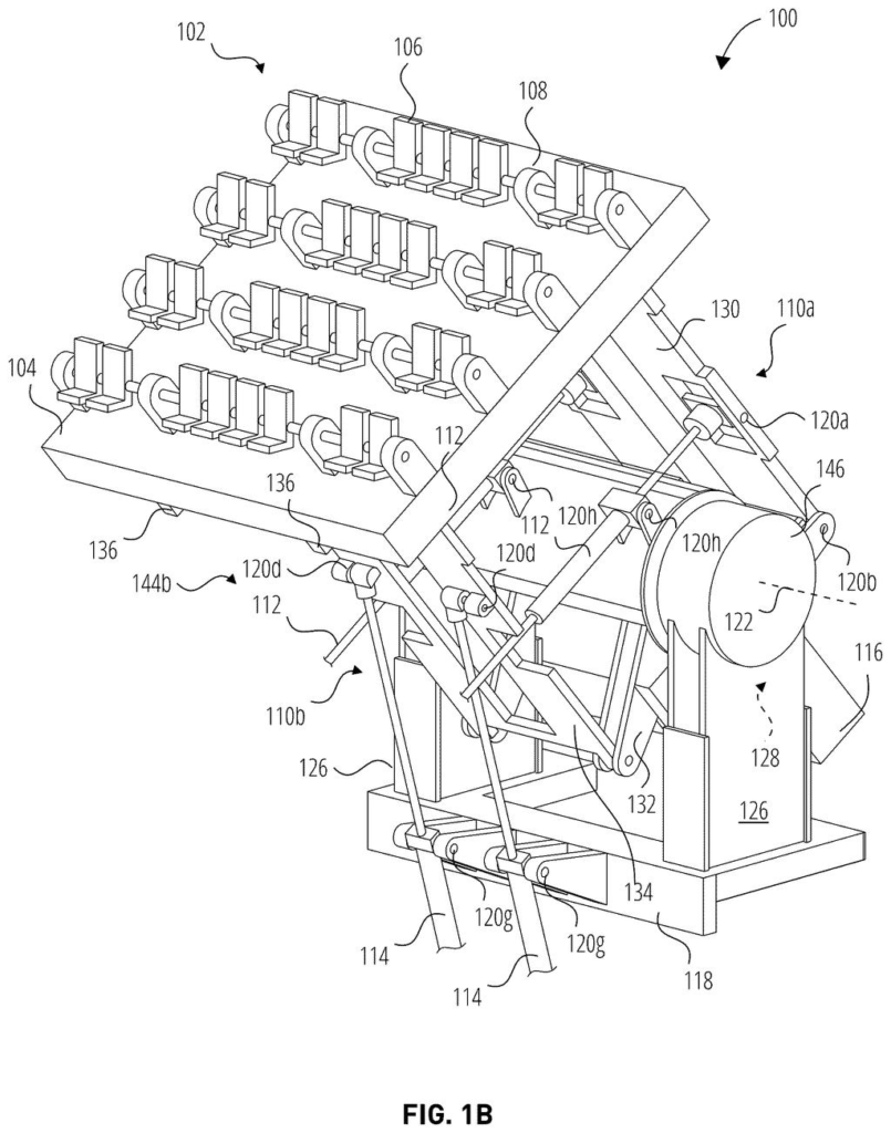
What Disney's tipping ride cabin actually does
Imagine rolling your wheelchair or stroller onto a perfectly flat platform, buckling in, and then feeling the whole thing tip upright until you're facing a giant screen. On that screen, an animated canoe drifts toward a waterfall, and your seat lurches forward right as it goes over.
That is the idea in this Disney patent application. The ride cabin starts as a level floor for boarding, then a big rotating hub swings it up to vertical. Once you're there, a set of jointed arms (called a linkage) can lift the cabin, drop it, or tilt it forward and back in step with the film, so you get the sensation of flying, falling or being launched.
A heavy counterweight does much of the lifting. If the power goes out or a part breaks, it also brings the cabin back down to the flat loading position on its own.
a user cabin moveable between a loading position and a plurality of additional positions; a hub coupled to the user cabin and configured to rotate about an axis to move the user cabin between the loading position and at least one additional position …
Translation: The ride vehicle moves from the boarding spot into various other orientations using a rotating central hub.
How the hub and jointed arms move the cabin
The claims cover a user cabin (the part you sit or stand in) that moves between a loading position and several other "show" positions. A hub, which is a large rotating joint, turns around an axis to swing the cabin from loading to a show position. Then a linkage, a set of rigid bars joined by pivots, moves the cabin from one show position to another.
In the main version the linkage is a four-bar linkage, and it is pushed by linear actuators (rods that extend and retract, like a piston). The joints sit slightly off-center, which creates lever arms. A small push at the end of a rod becomes a bigger, faster motion at the platform, so the cabin can heave or tilt farther than the rods could move it directly.
The filing also describes:
- Brakes (disc, hydraulic or electromagnetic) that lock the hub while you board and release it for the move.
- A counterweight that offsets the weight of riders and platform, so smaller, cheaper motors can be used.
- Seats on a pivot that stay upright while the platform rotates.
- A display whose visuals are coordinated with the cabin's movement.
Optional variations include anchoring the rods to a separate point for longer lever arms and bigger heaves, adding a gas-spring cylinder to carry more load, and using bars of unequal length to tilt the platform downward.
What this means for ride loading lines and upkeep
If it ever reaches a park, you would notice it first at the boarding gate. A flat, level floor makes getting on and off faster, and it removes a barrier for guests who use wheelchairs, canes or crutches. Faster loading means more riders per day, which is what shortens lines. The counterweight also returns the cabin to the loading position by itself if a motor breaks or power drops, which matters when a ride has to be emptied mid-show.
For Disney, the appeal is cost and upkeep. A counterweight allows smaller motors, and the jointed arms let crews swap a worn rod without rebuilding the ride. The application is at an early stage: the examiner's first review rejected the claims as filed, which is routine and usually followed by amendments. Nothing in it says a specific attraction is planned.
This is the ninth Disney filing we've tracked in our Display patents coverage since June, which already includes a dual-laser projection idea and a floating 3D image system.
Anyone who has stood in a long line knows the biggest bottleneck on a popular ride is people getting on and off. Disney's filing goes after that directly, with a floor that is flat and level for boarding. That also helps guests who use wheelchairs or canes.
The rest of the fix targets money and upkeep. A counterweight means smaller motors, and jointed arms let a crew replace one worn rod without taking the whole ride apart. Those costs add up for any park.
The size of the answer matches the size of the problem. It is plain mechanical engineering, and a ride that returns itself to the loading spot when the power dies addresses a worry any operator would have. Whether it ever appears in a park is a question the filing cannot answer.
Get our take in your Top Stories
Liked this breakdown? Add Patentlyze as a preferred source on Google, and our plain-English take shows up more often in your Top Stories the next time Disney patent news breaks.
There are more where this came from
We read every patent application Big Tech publishes and send you the ones worth knowing. Plain English, free, every week.
The drawings
15 drawing sheets from US 2026/0335777 A1 · click any drawing to enlarge


Show the other 7 sheets


Want this weekly breakdown for a company we don't cover? Patentlyze Pro →
Be the first to weigh in