
Samsung Patents a Screen Touch Design That Blocks Signal Disruption in Displays
When the wiring inside a touchscreen gets too close together, signals bleed into each other and the screen starts misreading your taps. Samsung's latest patent describes a way to add a shielding wire that wraps around the problem area before it starts.
What Samsung's auxiliary line touch sensor actually does
Touchscreens are built with a grid of tiny wires that detect where your finger lands. The closer those wires are packed, the more they can interfere with each other, causing the screen to misread taps or swipes, especially near the edges where sensing lines have to squeeze into a narrower border.
Samsung's patent describes adding an auxiliary line, essentially an extra wire connected to electrical ground, that traces around the sensing electrode wires in the problem zones. Think of it like a guardrail that absorbs stray electrical signals before they can bleed into a neighboring wire. There is also a dummy line, a wire that is not connected to anything, placed nearby to help balance the physical and electrical environment.
The goal is a touchscreen that reads your input more accurately, even in the tight spaces near the display's border, without requiring the electrodes themselves to be completely redesigned.
… a first sensing electrode and a second sensing electrode in the sensing area; a first sensing line electrically connected to the first sensing electrode; a second sensing line electrically connected to the second sensing electrode; a ground line; an auxiliary line electrically connected to the ground line; and a dummy line …
Translation: The screen layout uses specific electrodes, lines, and a ground connection to manage touch inputs.
How the auxiliary and dummy lines reduce signal crosstalk
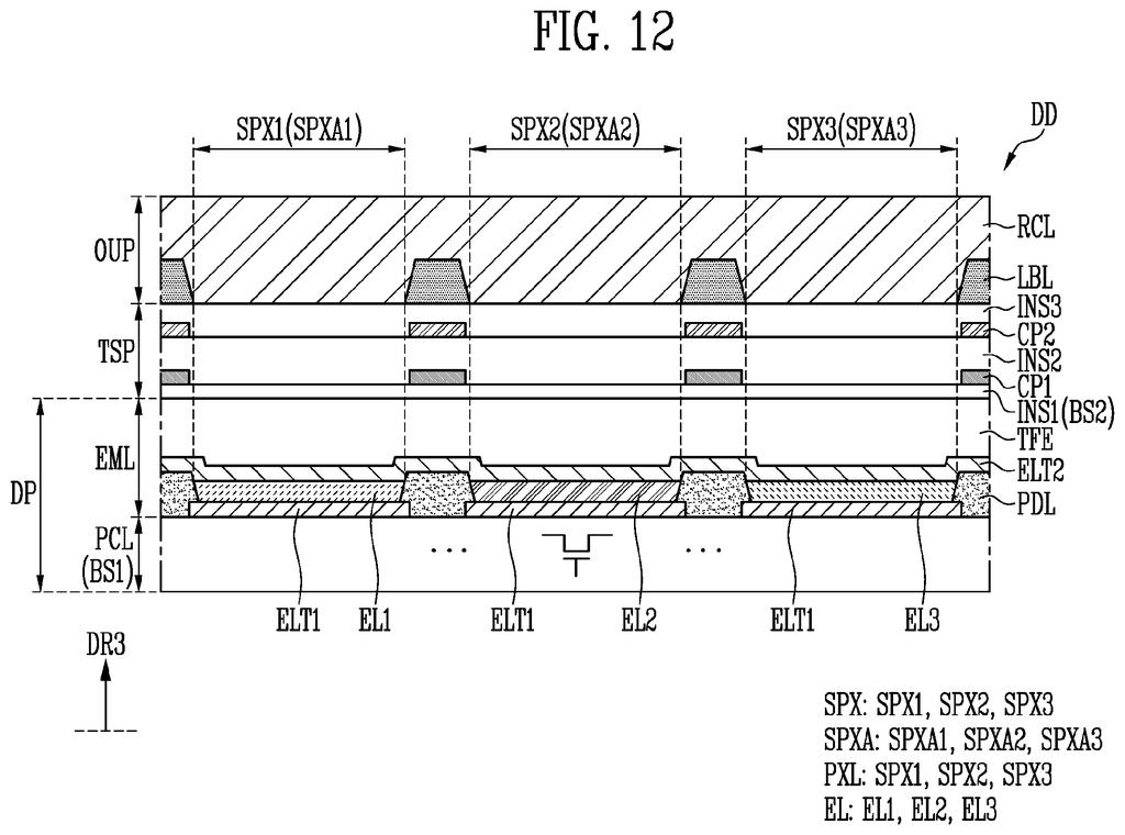
The patent describes a touch sensor layered on top of a display panel that contains light-emitting elements (like OLED pixels). The sensing area covers most of the screen, while the non-sensing area is the narrow border around it.
Inside the sensing area, two sets of electrodes sit on a thin base layer: first sensing electrodes and second sensing electrodes, which form the grid that detects touch. Each electrode type connects to its own sensing line, which carries the signal to the display's processing chip.
The key addition is the auxiliary line. It is connected to a ground line (a reference voltage that absorbs unwanted electrical noise) and is routed so that it:
- Overlaps the second sensing electrode when viewed from above
- Encloses at least part of the sensing line that runs through the sensing area (the 2-1-th sensing line in the patent's terminology)
- Connects electrically to the second sensing electrode itself
Separately, a dummy line runs nearby but is not connected to either set of electrodes. It acts as a passive spacer, helping keep the electrical environment consistent so that the active lines behave predictably. Together, these two additions are designed to reduce crosstalk, the phenomenon where a signal on one wire leaks into a neighboring wire and causes false touch readings.
The auxiliary line may overlap the second sensing electrode in a plan view, enclose at least a portion of the 2-1-th sensing line, and be electrically connected to the second sensing electrode.
Translation: An extra wire loops around the sensor components to shield them from electrical interference.
What this means for touch accuracy on Samsung screens
For everyday users, the payoff is straightforward: fewer phantom touches, more accurate edge-of-screen taps, and a display that responds the way you expect even when you are reaching for a button close to the bezel. As screens get thinner and bezels get narrower, the wiring inside has less room, and electrical interference becomes a bigger problem. A fix baked into the sensor layer itself is more reliable than trying to correct errors in software after they happen.
Samsung keeps filing on display sensor architecture, so this fits a broader pattern of incremental work on how its panels detect input. The design applies to any light-emitting display, including OLED, making it relevant across Samsung's phone, tablet, and monitor product lines rather than a niche fix for one device.
Samsung's 112th filing we've tracked in our display technology watchlist since May builds on work like the touch sensor balance patent and the dual-screen streaming application.
The fix here targets a frustrating but invisible problem: when you tap near the edge of a thin-bezel screen and the phone registers the wrong spot or nothing at all. That happens because the wires carrying touch signals get crowded together at the screen's border, and their electrical fields start interfering with each other. Samsung's solution wraps an extra grounded wire around the vulnerable section, acting as a physical barrier that keeps each signal clean and separate.
Most people will never know this component exists, and that anonymity is the point. A screen that consistently registers exactly where your finger lands, even in the corners, is simply a better screen.
There are more where this came from
We read every patent application Big Tech publishes and send you the ones worth knowing. Plain English, free, every week.
The drawings
20 drawing sheets from US 2026/0299722 A1 · click any drawing to enlarge


Want this weekly breakdown for a company we don't cover? Patentlyze Pro →
Be the first to weigh in