
Sony Files Patent to Help Surgical Cameras See Faint Glowing Dye More Clearly
Surgeons sometimes inject a dye that glows, but that glow can be much fainter than the normal view around it. Sony's filing gives a second sensor a share of the visible light so the faint glow has a better chance of showing up.
What Sony's two-sensor surgical camera does
Ever tried to spot a glow-in-the-dark sticker in a brightly lit room? The glow is there, but the room light drowns it out. Surgeons run into a version of this: some operations use a dye that glows under special light to highlight tissue, and that glow can be weak next to the normal view of the body.
Sony's filing tweaks the prism inside a surgical camera, the glass block that splits incoming light and sends each part to a different sensor. Older designs send all the visible light to one sensor and all the invisible infrared light to another. Sony's version sends a share of the visible light to each sensor, for example half and half, so the second sensor can help catch the faint glow.
The split can be tuned. If the glow is weak, more visible light goes to the second sensor (up to 80 percent). If it is strong, more goes to the regular sensor for a cleaner normal picture. Meanwhile, more than 90 percent of the infrared light still goes straight to its own sensor.
An imaging device comprising: a prism configured to separate visible light and special light from each other, the visible light and the special light included in light from an observation target; …
Translation: The camera uses a specialized prism to split normal light from the glowing dye light.
How the prism splits light between sensors
The core part is a prism: a glass block with a thin coating between its two halves. That coating is called a dichroic film (a layer that reflects some colors of light and lets others pass). Older medical cameras use a coating that sends all visible light to one sensor and all near-infrared light (invisible light just beyond red) to another. Sony's coating reflects only part of the visible light and passes the rest.
Claim 1 sets two numbers:
- The amount of visible light reaching the second sensor, divided by the amount reaching the first, must fall between 0.25 and 4. That works out to anything from a 20/80 split to an 80/20 split.
- More than 90 percent of the near-infrared light must reach the second sensor.
The description's example is an even 50/50 split. When the glow from the dye is weak, the design can lean toward the second sensor. When it is strong, it can lean the other way. A band pass filter (a filter that only lets chosen colors through) in front of the second sensor blocks the normal visible light and lets the glow through. The light source flashes white light and excitation light (light that makes the dye glow) at different moments.
A second version, covered by claim 12, adds a third sensor just for the visible glow. The filing also describes a depolarizer (a part that evens out the light's orientation so brightness stays steady), limits on sensor pixel sizes, and ways to position each sensor so they all stay in focus together.
… spectral transmittance of the special light toward the special light imaging sensor in the prism is greater than 90%.
Translation: The prism allows over ninety percent of the faint dye glow to reach its dedicated sensor.
Why dim surgical dye glow is a hard problem
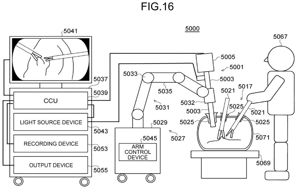
If you ever have surgery that uses glowing dye, the camera's job is to show the surgeon what that dye is marking. A faint glow is easy to lose, so a design that gives the weak signal more light to work with could make it easier to see. The filing describes endoscopes (thin cameras that go inside the body) and surgical microscopes as the places this would fit.
It is also a change to hardware that already exists. Dual-sensor prism cameras are the starting point, and the fix is mostly in how the coating divides the light. The filing names no product and says nothing about a release, so treat it as a look at how Sony is thinking about medical camera design.
Sony's 84th filing in our camera patent coverage since May follows work on stabilized video appearance and cross-frame body tracking, adding to a run of camera ideas we've tracked.
Claim 1 comes down to a window of numbers. The visible light can be divided between the two sensors anywhere from 20/80 to 80/20, and more than 90 percent of the infrared must reach its own sensor. That window is wide: it covers an even split and both lopsided versions the description talks about.
Claim 1 never mentions dye, glow or surgery. Those show up in the description and in claim 20, which adds a surgical site. As worded, claim 1 would match any prism camera with two sensors whose numbers land inside that window. A camera that sends all visible light one way falls outside it.
Bottom line: it is a modest change to a coating, so it should fit into existing camera layouts, and the wide range gives Sony room to tune for brighter or fainter dyes. It will not change daily life, but for the operating room it is a sensible fix for a real problem.
Get our take in your Top Stories
Liked this breakdown? Add Patentlyze as a preferred source on Google, and our plain-English take shows up more often in your Top Stories the next time Sony patent news breaks.
There are more where this came from
We read every patent application Big Tech publishes and send you the ones worth knowing. Plain English, free, every week.
The drawings
14 drawing sheets from US 2026/0324951 A1 · click any drawing to enlarge


Show the other 6 sheets


Want this weekly breakdown for a company we don't cover? Patentlyze Pro →
Be the first to weigh in