
Meta · Filed Apr 30, 2026 · Published Nov 5, 2026

Meta Files Patent for AR Glasses That Show a Wider View Through Cheaper Glass

Meta's latest filing slants the tiny light-bending patterns inside an AR glasses lens. Its own simulations say that tilt could widen the view from about 27 degrees to 90 on plain glass.
A smart glasses lens routes colored light across the glass to show a wider picture to the wearer. Drawing from patent filing US 2026/0349260 A1.
A smart glasses lens routes colored light across the glass to show a wider picture to the wearer.
See all 62 drawings from this filing ↓
Publication number US 2026/0349260 A1 US20260349260A1
Applicant Meta Platforms Technologies, LLC
Filing date Apr 30, 2026
Publication date Nov 5, 2026
Inventors Andrew Maimone, Mohamed Tarek Ahmed El-Haddad, Yimin Ding, Xinyu Zhu, Yun-Han Lee, Sangho Lee, Don Gyou Lee, You-Ren Lan, Yuhsuan Li, Linghui Rao, Shenglin Ye, John-John Van Den Bergh, Harsha Vijay Shah, Janne Hyyti, Hee Yoon Lee, Alejo Lifschitz Arribio, Christina Spaegele
US classification 385/37
Status when we published Waiting for an examiner (Sep 15, 2026)
Parent application Claims priority from a provisional application 63797514 (filed 2025-04-30)
Document 20 claims

What Meta's tilted-layer AR lens actually does

Ever tried to watch a movie through a mail slot? That is roughly what many AR glasses offer today: digital images float in a small window in front of you, and everything outside it goes blank.

The trouble is physics. The glass that carries the image to your eye limits how wide that window can be, and the glass that makes it wide is rare and very expensive. Meta's patent filing gets around the limit by placing tiny light-bending patterns inside the lens, tilted at a slant, instead of laying them flat like a sticker. The tilt squeezes a wide view into the narrow range of angles ordinary glass can carry.

The filing says this could give a 90-degree view in low-cost glass, for one color of light, where flat designs top out around 27 degrees. The same trick could also help the glasses watch your eyes.

From the filing · CLAIM 1
… a plurality of grating elements physically tilted inside the waveguide media such that none of the grating elements are planarly parallel to the opposed outer surfaces of the waveguide media.

Translation: Tiny internal optical structures are intentionally slanted at an angle instead of running flat along the glass.

How light bends inside Meta's slanted lens

The core piece is a waveguide, a thin see-through plate that carries light from a tiny projector at the edge of the frame to your eye. Inside it sit gratings (microscopic patterns that bend light). Claim 1 covers placing them at a slant inside the plate, so that none sits flat and parallel to the plate's two outer faces.

A flat grating can only handle the range of angles the glass can trap and carry, and that range shrinks as the glass gets cheaper (its index of refraction, a measure of how strongly it bends light, is lower). A tilted grating squeezes a wide set of incoming angles into that smaller range. The claims mention glass with an index no higher than 1.52, and a view at least fifty degrees wide.

The same plate can do two jobs:

  • Showing the image: copying it many times across the plate (pupil replication) so you still see it when your eye moves.
  • Eye tracking: catching light bounced off your eye and steering it to a tiny camera. The filing's example images eight test points, against four for a flat design.

The filing sketches three ways to build it: stacking and slicing, molding two halves, or exposing light-sensitive material. Two other independent claims cover a backlight film with unevenly spaced pyramids that cuts interference ripples on a headset's LCD screen, and a way to print lenses onto glass over a pre-applied adhesive layer.

Why a cheaper lens matters for AR glasses

If you have ever tried AR glasses, you know the catch: you get either a tiny floating window or a bulky, pricey headset. A wider view on ordinary glass points toward lighter, cheaper glasses that show more of the digital world at once, which is what most people expect from them.

The eye-tracking side matters too. A camera that stays out of your sight yet still sees your whole eye could help glasses adjust what they show based on where you look. Keep in mind this is a patent application, so none of it is a product, and the headline numbers come from simulations.

Meta's 80th filing we've tracked in our AR glasses work since May adds to a run that includes a detachable menu bar and a tiny vibrating mirror.

Editorial take

The narrow field of view in AR glasses is not a minor annoyance. It is the reason most people who try them feel like peering through a mail slot, and it is the core reason the technology stays a curiosity rather than becoming something people actually wear.

Meta's approach here attacks the geometry of the glass layer itself, which is the right place to look for a problem this fundamental. The wide view shown in the filing comes from computer simulation at a single color, and the target shrinks considerably once a full color image is required, so the gap between promising diagram and wearable product remains large.

The smaller fixes in the filing, for screen ripple and lens warping during production, are modest and practical. The main idea carries a much heavier burden and has much further to travel before someone can wear the result to the grocery store.

Get our take in your Top Stories

Liked this breakdown? Add Patentlyze as a preferred source on Google, and our plain-English take shows up more often in your Top Stories the next time Meta patent news breaks.

There are more where this came from

We read every patent application Big Tech publishes and send you the ones worth knowing. Plain English, free, every week.

The drawings

62 drawing sheets from US 2026/0349260 A1 · click any drawing to enlarge

Steps for embedding tilted optical gratings inside headset glass, drawing sheet 1 from US 2026/0349260 A1
Sheet 1 Steps for embedding tilted optical gratings inside headset glass
Tilted internal elements guiding light through a smart glasses lens, drawing sheet 2 from US 2026/0349260 A1
Sheet 2 Tilted internal elements guiding light through a smart glasses lens
Tilting a grating element bends light at wider angles, drawing sheet 3 from US 2026/0349260 A1
Sheet 3 Tilting a grating element bends light at wider angles
Comparing how three lens types bend incoming display rays, drawing sheet 4 from US 2026/0349260 A1
Sheet 4 Comparing how three lens types bend incoming display rays
Field of view limits across different lens materials, drawing sheet 5 from US 2026/0349260 A1
Sheet 5 Field of view limits across different lens materials
Spherical models mapping incoming light angles through the lens, drawing sheet 6 from US 2026/0349260 A1
Sheet 6 Spherical models mapping incoming light angles through the lens
Projector light entering the edge of the glasses lens, drawing sheet 7 from US 2026/0349260 A1
Sheet 7 Projector light entering the edge of the glasses lens
How the lens spreads light across a wide angle, drawing sheet 8 from US 2026/0349260 A1
Sheet 8 How the lens spreads light across a wide angle
Show the other 52 sheets
How light of different colors spreads through the lens, drawing sheet 9 from US 2026/0349260 A1
Sheet 9 How light of different colors spreads through the lens
Mapping light angles to prevent double vision and ghost images, drawing sheet 10 from US 2026/0349260 A1
Sheet 10 Mapping light angles to prevent double vision and ghost images
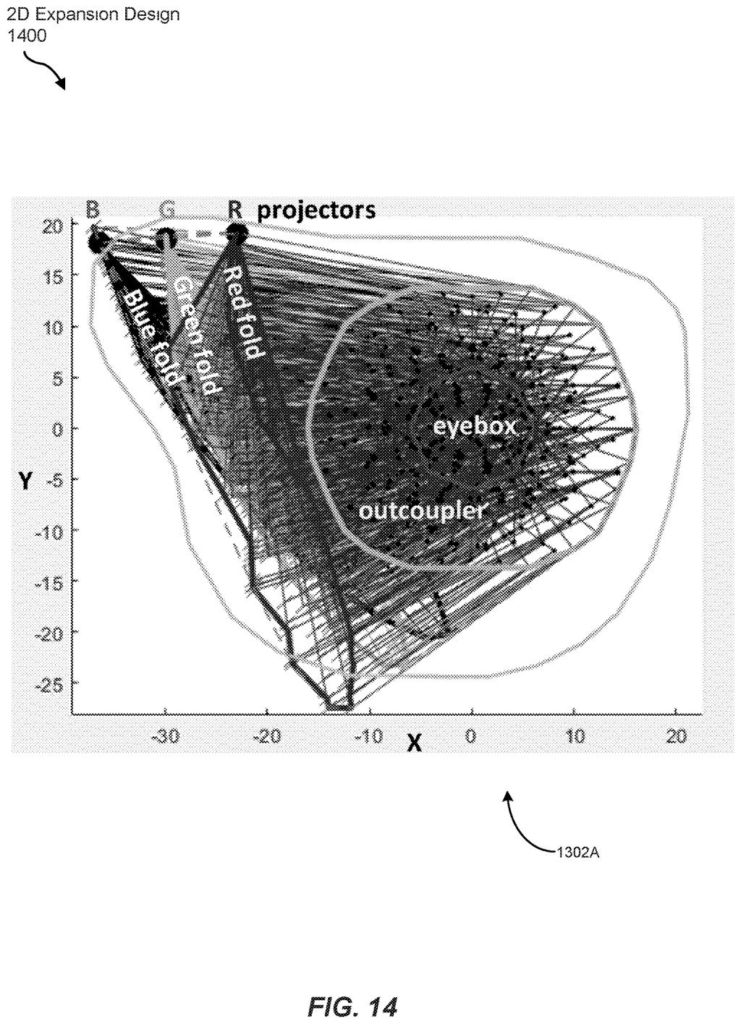
Routing paths that expand projector images across the glass, drawing sheet 11 from US 2026/0349260 A1
Sheet 11 Routing paths that expand projector images across the glass
Target view angles and frame dimensions for everyday smart glasses, drawing sheet 12 from US 2026/0349260 A1
Sheet 12 Target view angles and frame dimensions for everyday smart glasses
Two layout options for bouncing light into the viewing area, drawing sheet 13 from US 2026/0349260 A1
Sheet 13 Two layout options for bouncing light into the viewing area
Combining separate red, green, and blue beams into the eye, drawing sheet 14 from US 2026/0349260 A1
Sheet 14 Combining separate red, green, and blue beams into the eye
Calculating the tilt angles needed to steer each color, drawing sheet 15 from US 2026/0349260 A1
Sheet 15 Calculating the tilt angles needed to steer each color
Tracing full color images through the curved glass lens, drawing sheet 16 from US 2026/0349260 A1
Sheet 16 Tracing full color images through the curved glass lens
Light bouncing through the lens to form an expanded picture, drawing sheet 17 from US 2026/0349260 A1
Sheet 17 Light bouncing through the lens to form an expanded picture
Bending eye reflections back into the lens for gaze tracking, drawing sheet 18 from US 2026/0349260 A1
Sheet 18 Bending eye reflections back into the lens for gaze tracking
How wide the camera sees your eye through glass, drawing sheet 19 from US 2026/0349260 A1
Sheet 19 How wide the camera sees your eye through glass
Testing how the lens captures distinct points across the eye, drawing sheet 20 from US 2026/0349260 A1
Sheet 20 Testing how the lens captures distinct points across the eye
Distorted eye positions captured by the camera before correction, drawing sheet 21 from US 2026/0349260 A1
Sheet 21 Distorted eye positions captured by the camera before correction
Adjusting the optical elements to improve gaze capture angles, drawing sheet 22 from US 2026/0349260 A1
Sheet 22 Adjusting the optical elements to improve gaze capture angles
Clearer spot alignment produced by the updated lens design, drawing sheet 23 from US 2026/0349260 A1
Sheet 23 Clearer spot alignment produced by the updated lens design
Smart glasses made with wide lenses and eye cameras, drawing sheet 24 from US 2026/0349260 A1
Sheet 24 Smart glasses made with wide lenses and eye cameras
Front and side views of a virtual reality headset, drawing sheet 25 from US 2026/0349260 A1
Sheet 25 Front and side views of a virtual reality headset
Parts of a headset that direct light and track gaze, drawing sheet 26 from US 2026/0349260 A1
Sheet 26 Parts of a headset that direct light and track gaze
Tracking a wearer's gaze using reflections off the eye, drawing sheet 27 from US 2026/0349260 A1
Sheet 27 Tracking a wearer's gaze using reflections off the eye
Connecting smart glasses and other devices over the cloud, drawing sheet 28 from US 2026/0349260 A1
Sheet 28 Connecting smart glasses and other devices over the cloud
Hardware inside client devices and supporting web servers, drawing sheet 29 from US 2026/0349260 A1
Sheet 29 Hardware inside client devices and supporting web servers
Layered optical sheets inside a screen backlight unit, drawing sheet 30 from US 2026/0349260 A1
Sheet 30 Layered optical sheets inside a screen backlight unit
Textured film shaped with pyramids on top and ridges below, drawing sheet 31 from US 2026/0349260 A1
Sheet 31 Textured film shaped with pyramids on top and ridges below
Randomizing pyramid cutting paths to prevent visual interference ripples, drawing sheet 32 from US 2026/0349260 A1
Sheet 32 Randomizing pyramid cutting paths to prevent visual interference ripples
Shifting prism rows by equal offsets prevents screen distortion, drawing sheet 33 from US 2026/0349260 A1
Sheet 33 Shifting prism rows by equal offsets prevents screen distortion
Staggering prism rows with uneven shifts stops screen interference, drawing sheet 34 from US 2026/0349260 A1
Sheet 34 Staggering prism rows with uneven shifts stops screen interference
Offsetting grouped prism blocks equally across the backlight surface, drawing sheet 35 from US 2026/0349260 A1
Sheet 35 Offsetting grouped prism blocks equally across the backlight surface
Variable spacing between grouped prism blocks breaks visual interference, drawing sheet 36 from US 2026/0349260 A1
Sheet 36 Variable spacing between grouped prism blocks breaks visual interference
Tightly nested prism clusters shifted by a fixed distance, drawing sheet 37 from US 2026/0349260 A1
Sheet 37 Tightly nested prism clusters shifted by a fixed distance
Unevenly spaced prism clusters designed to eliminate display patterns, drawing sheet 38 from US 2026/0349260 A1
Sheet 38 Unevenly spaced prism clusters designed to eliminate display patterns
Separated clusters of pinwheel prisms distributed across the film, drawing sheet 39 from US 2026/0349260 A1
Sheet 39 Separated clusters of pinwheel prisms distributed across the film
Tilting adjacent prisms at slight angles prevents backlight glare, drawing sheet 40 from US 2026/0349260 A1
Sheet 40 Tilting adjacent prisms at slight angles prevents backlight glare
Angling microprism rows to prevent distracting screen glare, drawing sheet 41 from US 2026/0349260 A1
Sheet 41 Angling microprism rows to prevent distracting screen glare
Shifting tilted prism rows apart prevents display patterns, drawing sheet 42 from US 2026/0349260 A1
Sheet 42 Shifting tilted prism rows apart prevents display patterns
Variable row spacing stops light interference across the screen, drawing sheet 43 from US 2026/0349260 A1
Sheet 43 Variable row spacing stops light interference across the screen
Grouping tilted prisms into clusters cleans up screen artifacts, drawing sheet 44 from US 2026/0349260 A1
Sheet 44 Grouping tilted prisms into clusters cleans up screen artifacts
Staggering prism blocks prevents distracting grid reflections, drawing sheet 45 from US 2026/0349260 A1
Sheet 45 Staggering prism blocks prevents distracting grid reflections
Rotating prism clusters apart eliminates screen distortion, drawing sheet 46 from US 2026/0349260 A1
Sheet 46 Rotating prism clusters apart eliminates screen distortion
Scattering prism clusters across the backlight stops visual noise, drawing sheet 47 from US 2026/0349260 A1
Sheet 47 Scattering prism clusters across the backlight stops visual noise
Wavy prism row spacing smooths out harsh display glare, drawing sheet 48 from US 2026/0349260 A1
Sheet 48 Wavy prism row spacing smooths out harsh display glare
Curved backlight patterns that prevent distracting display interference, drawing sheet 49 from US 2026/0349260 A1
Sheet 49 Curved backlight patterns that prevent distracting display interference
Clear adhesive layers tested to stop printed lenses from warping, drawing sheet 50 from US 2026/0349260 A1
Sheet 50 Clear adhesive layers tested to stop printed lenses from warping
Starting base material for building light filtering smart glasses, drawing sheet 51 from US 2026/0349260 A1
Sheet 51 Starting base material for building light filtering smart glasses
Tuning crystal orientation inside the raw optical sheet, drawing sheet 52 from US 2026/0349260 A1
Sheet 52 Tuning crystal orientation inside the raw optical sheet
Etching microscopic ridges across the optical surface, drawing sheet 53 from US 2026/0349260 A1
Sheet 53 Etching microscopic ridges across the optical surface
Filling etched grooves to create a polarization filter, drawing sheet 54 from US 2026/0349260 A1
Sheet 54 Filling etched grooves to create a polarization filter
Incoming light waves striking the layered optical filter, drawing sheet 55 from US 2026/0349260 A1
Sheet 55 Incoming light waves striking the layered optical filter
Flat light waves passing evenly through the optical layer, drawing sheet 56 from US 2026/0349260 A1
Sheet 56 Flat light waves passing evenly through the optical layer
Alternating strips built to split light waves by direction, drawing sheet 57 from US 2026/0349260 A1
Sheet 57 Alternating strips built to split light waves by direction
Layering the light filter over a crystalline base, drawing sheet 58 from US 2026/0349260 A1
Sheet 58 Layering the light filter over a crystalline base
Tracking how different light angles move through the glass, drawing sheet 59 from US 2026/0349260 A1
Sheet 59 Tracking how different light angles move through the glass
Blending in a smooth top layer for horizontal waves, drawing sheet 60 from US 2026/0349260 A1
Sheet 60 Blending in a smooth top layer for horizontal waves

Sheets 61 to 62 are in the full USPTO filing.

Browse all the drawings 62 drawing sheets
Patent filing page

Source. Full patent text and figures from the official USPTO publication PDF.
Reader comments

Be the first to weigh in

Start the discussion

Real name or a handle, either is fine. Comments are read by a person before they appear, so allow a little time. Keep it about the filing.