
Samsung · Filed Jul 15, 2026 · Published Nov 5, 2026

Samsung Files Patent for Screens With Holes That Keep Moisture Out

If your screen has a hole in it for a camera, the edge of that hole is an open door for damp air. Samsung's answer is to dig tiny moats with overhanging lips around it.
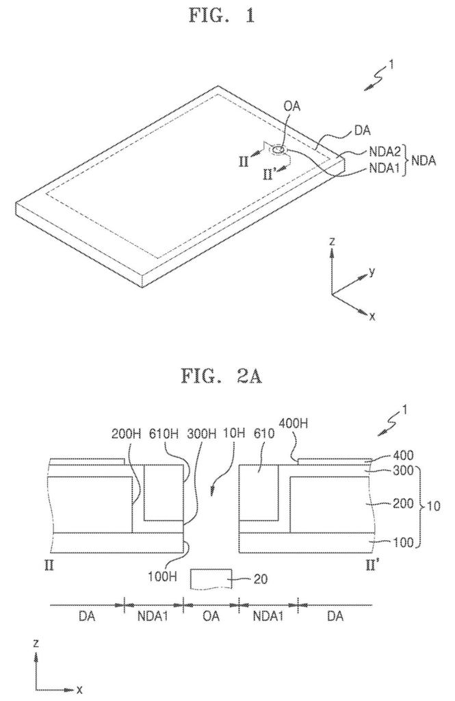
A smartphone screen featuring an opening for a front-facing camera designed to seal inner display layers against moisture. Drawing from patent filing US 2026/0349551 A1.
A smartphone screen featuring an opening for a front-facing camera designed to seal inner display layers against moisture.
See all 50 drawings from this filing ↓
Publication number US 2026/0349551 A1 US20260349551A1
Applicant SAMSUNG DISPLAY CO., LTD.
Filing date Jul 15, 2026
Publication date Nov 5, 2026
Inventors WOOYONG SUNG, WONWOO CHOI, SOOYOUN KIM, JUNGHAN SEO, SEOYEON LEE, HYOUNGSUB LEE, MOONWON CHANG, SEUNGGUN CHAE, SEUNGYONG SONG
US classification 345/174
Status when we published Waiting for an examiner (Jul 29, 2026)
Parent application is a Continuation of 19275657 (filed 2025-07-21)
Document 19 claims

What Samsung's screen-hole trenches actually do

Every time your phone sits in a steamy bathroom or a damp pocket, moisture is looking for a way into the screen. A display with a hole in it, for a camera or sensor, gives that moisture an extra doorway along the hole's edge.

Samsung's new patent application describes a fix: dig narrow, ring-shaped trenches around the hole, each with an overhanging lip like the eaves of a roof. When the light-producing layers of the screen are laid down, they snap apart at those lips, so moisture has no unbroken path toward your pixels.

The same trenches help when the hole is cut out. A crack that starts at the cut runs out of road before it reaches the part of the screen you actually look at. Sealing layers then cover everything on top.

From the filing · CLAIM 1
forming a groove in the first non-display area by etching a stacked structure of a first layer located in the first non-display area and a second layer directly on the first layer, wherein the second layer includes a tip protruding further toward the groove than a lateral surface of the first layer in a cross-sectional view …

Translation: Workers carve a tiny trench with an overhanging lip to block moisture from reaching the screen electronics.

How the overhanging lip splits the glowing layers

The claims cover a manufacturing method for a display panel with a hole (the "open area"), a ring of non-glowing border around it, and the glowing display area beyond. First, a groove is etched into that border through a stack of two layers: a lower one, and an upper one whose edge sticks out past it. That sticking-out edge is the tip, and it gives the groove an undercut shape, wider underneath than at the opening.

Next the screen's light-producing parts are built: a pixel electrode, an intermediate layer holding the light-emitting layer, and a top electrode. Because these organic layers are laid down as one sheet, the tip breaks them into separate pieces, so no unbroken organic path runs from the hole to the pixels. In the description, the tips stick out about 0.7 to 1.5 micrometers (far thinner than a hair), and the lower layer is a polymer resin.

Then comes encapsulation, a sealing coat against moisture:

  • A first inorganic layer coats the grooves without breaking.
  • An organic layer is made by applying a liquid plastic ingredient (a monomer) and hardening it, with a partition wall steering where the liquid flows.
  • A second inorganic layer goes on top and touches the first.

One version adds a flattening layer at least about 5 micrometers thick over the grooves. Another uses a broken ring of conductive material as a wire, so a crack would show up as a lost signal.

From the filing · THE ABSTRACT
… a thin-film encapsulation layer disposed on the display element layer, the thin-film encapsulation layer including a first inorganic encapsulation layer, an organic encapsulation layer, and a second inorganic encapsulation layer which are sequentially stacked …

Translation: Layers of organic and inorganic materials are stacked on top to seal the sensitive parts of the display.

Why Samsung's hole-punch screens need these moats

Holes in screens are getting used for more than selfie cameras. The filing lists infrared sensors, microphones, speakers, and even a clock hand on a smartwatch or a car's instrument panel. Every one of those holes is a weak spot where water vapor can sneak in and cracks can start. A design that blocks both could mean panels that keep their brightness longer and survive the cutting step in the factory.

You would never see any of this in a product photo. It is a factory-line detail, and the benefit shows up as fewer dead spots near the hole over time. This application is also the latest in a long chain of continuations that trace back to Korean filings from 2018, so the idea has been refined over years.

Samsung's 131st filing we've tracked in our display technology watchlist since May follows one on hover-vs-finger detection and one on self-crossing wiring.

Editorial take

Every moat costs something. Here the price is space and precision: the rings eat into the border around the hole, and each overhanging lip is only about a micrometer wide in the filing's examples. The factory has to hit that shape every time, with extra etching steps to get there.

The description also admits weak spots. Metal layers laid on top can come out thin or broken around the lips, and stray bits of hardened coating can end up inside a trench. Samsung's remedy is more covering layers, which adds even more steps to the build.

Still, the trade reads as worth it. A hole in a screen is a hole in its armor, and a few thin rings of extra border is a small price for pixels that stay bright and a panel that survives being cut. The risk sits in manufacturing yield, which this document cannot tell us anything about.

Get our take in your Top Stories

Liked this breakdown? Add Patentlyze as a preferred source on Google, and our plain-English take shows up more often in your Top Stories the next time Samsung patent news breaks.

There are more where this came from

We read every patent application Big Tech publishes and send you the ones worth knowing. Plain English, free, every week.

The drawings

50 drawing sheets from US 2026/0349551 A1 · click any drawing to enlarge

A screen cutout makes room for the camera, drawing sheet 1 from US 2026/0349551 A1
Sheet 1 A screen cutout makes room for the camera
Cameras can sit inside or under screen cutouts, drawing sheet 2 from US 2026/0349551 A1
Sheet 2 Cameras can sit inside or under screen cutouts
Display wiring routes around the camera opening across the phone, drawing sheet 3 from US 2026/0349551 A1
Sheet 3 Display wiring routes around the camera opening across the phone
Display wires curve around the camera hole safely, drawing sheet 4 from US 2026/0349551 A1
Sheet 4 Display wires curve around the camera hole safely
Protective grooves trap moisture around the camera opening, drawing sheet 5 from US 2026/0349551 A1
Sheet 5 Protective grooves trap moisture around the camera opening
Layered seals keep moisture away from screen pixels, drawing sheet 6 from US 2026/0349551 A1
Sheet 6 Layered seals keep moisture away from screen pixels
Protective coats cover the light-emitting parts to prevent water damage, drawing sheet 7 from US 2026/0349551 A1
Sheet 7 Protective coats cover the light-emitting parts to prevent water damage
Etched trenches with overhanging edges block water before cutting holes, drawing sheet 8 from US 2026/0349551 A1
Sheet 8 Etched trenches with overhanging edges block water before cutting holes
Show the other 42 sheets
Protective coatings flow into dams to block moisture from entering, drawing sheet 9 from US 2026/0349551 A1
Sheet 9 Protective coatings flow into dams to block moisture from entering
Smoothing material fills grooves before camera hole cutting, drawing sheet 10 from US 2026/0349551 A1
Sheet 10 Smoothing material fills grooves before camera hole cutting
Cutting the camera hole two ways leaves different edge profiles, drawing sheet 11 from US 2026/0349551 A1
Sheet 11 Cutting the camera hole two ways leaves different edge profiles
Rings of protective resin encircle the camera opening, drawing sheet 12 from US 2026/0349551 A1
Sheet 12 Rings of protective resin encircle the camera opening
Touch sensors use a diamond grid wired to bottom connectors, drawing sheet 13 from US 2026/0349551 A1
Sheet 13 Touch sensors use a diamond grid wired to bottom connectors
Upper touch sensor wires reach down through holes to connect, drawing sheet 14 from US 2026/0349551 A1
Sheet 14 Upper touch sensor wires reach down through holes to connect
Fine mesh patterns make up the lower touch sensor diamonds, drawing sheet 15 from US 2026/0349551 A1
Sheet 15 Fine mesh patterns make up the lower touch sensor diamonds
Dual mesh layers line up to detect screen touches reliably, drawing sheet 16 from US 2026/0349551 A1
Sheet 16 Dual mesh layers line up to detect screen touches reliably
Touch sensing grids patterned along different screen directions, drawing sheet 17 from US 2026/0349551 A1
Sheet 17 Touch sensing grids patterned along different screen directions
Stacked touch sensing lines separated by an insulating layer, drawing sheet 18 from US 2026/0349551 A1
Sheet 18 Stacked touch sensing lines separated by an insulating layer
Adding an extra sealing groove around the camera cutout, drawing sheet 19 from US 2026/0349551 A1
Sheet 19 Adding an extra sealing groove around the camera cutout
Extending the protective coating right to the hole border, drawing sheet 20 from US 2026/0349551 A1
Sheet 20 Extending the protective coating right to the hole border
Built-in barrier walls that prevent moisture from creeping in, drawing sheet 21 from US 2026/0349551 A1
Sheet 21 Built-in barrier walls that prevent moisture from creeping in
Multiple protective coatings shielding the screen layers from air, drawing sheet 22 from US 2026/0349551 A1
Sheet 22 Multiple protective coatings shielding the screen layers from air
Carving sealing trenches into the base glass at different depths, drawing sheet 23 from US 2026/0349551 A1
Sheet 23 Carving sealing trenches into the base glass at different depths
Layering moisture seals over the etched trenches around the cutout, drawing sheet 24 from US 2026/0349551 A1
Sheet 24 Layering moisture seals over the etched trenches around the cutout
Protective layers lining a trench to stop moisture leaks, drawing sheet 25 from US 2026/0349551 A1
Sheet 25 Protective layers lining a trench to stop moisture leaks
Smoothing material spread across trenches near the camera hole, drawing sheet 26 from US 2026/0349551 A1
Sheet 26 Smoothing material spread across trenches near the camera hole
Filler completely covering a trench to block liquid seepage, drawing sheet 27 from US 2026/0349551 A1
Sheet 27 Filler completely covering a trench to block liquid seepage
Cutting out the camera hole through the sealed display layers, drawing sheet 28 from US 2026/0349551 A1
Sheet 28 Cutting out the camera hole through the sealed display layers
Continuous rings surrounding the camera hole to shield pixels, drawing sheet 29 from US 2026/0349551 A1
Sheet 29 Continuous rings surrounding the camera hole to shield pixels
Multiple barrier rings encircling the camera cutout, drawing sheet 30 from US 2026/0349551 A1
Sheet 30 Multiple barrier rings encircling the camera cutout
Notched barrier rings routed around electrical wiring, drawing sheet 31 from US 2026/0349551 A1
Sheet 31 Notched barrier rings routed around electrical wiring
An alternative cut line exposing barrier edges near the hole, drawing sheet 32 from US 2026/0349551 A1
Sheet 32 An alternative cut line exposing barrier edges near the hole
Moisture barrier layers lining the inner groove walls, drawing sheet 33 from US 2026/0349551 A1
Sheet 33 Moisture barrier layers lining the inner groove walls
Protective rings surrounding the camera hole and display edges, drawing sheet 34 from US 2026/0349551 A1
Sheet 34 Protective rings surrounding the camera hole and display edges
Grooves near the screen outer edge blocking moisture flow, drawing sheet 35 from US 2026/0349551 A1
Sheet 35 Grooves near the screen outer edge blocking moisture flow
Three trench barriers sealing the area around the hole, drawing sheet 36 from US 2026/0349551 A1
Sheet 36 Three trench barriers sealing the area around the hole
Overhanging tips inside the groove to break liquid spread, drawing sheet 37 from US 2026/0349551 A1
Sheet 37 Overhanging tips inside the groove to break liquid spread
Adding a fourth groove to improve protection near the hole, drawing sheet 38 from US 2026/0349551 A1
Sheet 38 Adding a fourth groove to improve protection near the hole
Widened groove design extending closer to the hole edge, drawing sheet 39 from US 2026/0349551 A1
Sheet 39 Widened groove design extending closer to the hole edge
An extra dam barrier placed beside the internal circuitry, drawing sheet 40 from US 2026/0349551 A1
Sheet 40 An extra dam barrier placed beside the internal circuitry
Protective barriers surrounding a camera cutout to stop water leaks, drawing sheet 41 from US 2026/0349551 A1
Sheet 41 Protective barriers surrounding a camera cutout to stop water leaks
Sealant filling the deepest trench beside the camera hole, drawing sheet 42 from US 2026/0349551 A1
Sheet 42 Sealant filling the deepest trench beside the camera hole
Detailed cross sections showing moisture blocks stacked inside a groove, drawing sheet 43 from US 2026/0349551 A1
Sheet 43 Detailed cross sections showing moisture blocks stacked inside a groove
Continuous coating shielding the screen border from moisture, drawing sheet 44 from US 2026/0349551 A1
Sheet 44 Continuous coating shielding the screen border from moisture
Narrow grooves carved around the camera opening, drawing sheet 45 from US 2026/0349551 A1
Sheet 45 Narrow grooves carved around the camera opening
Touch wires routing screen signals past the camera hole, drawing sheet 46 from US 2026/0349551 A1
Sheet 46 Touch wires routing screen signals past the camera hole
A single barrier blocking liquid from entering the screen, drawing sheet 47 from US 2026/0349551 A1
Sheet 47 A single barrier blocking liquid from entering the screen
Overhanging groove edges designed to stop liquid flow, drawing sheet 48 from US 2026/0349551 A1
Sheet 48 Overhanging groove edges designed to stop liquid flow
Grooves surrounding a top-edge camera cutout to block moisture, drawing sheet 49 from US 2026/0349551 A1
Sheet 49 Grooves surrounding a top-edge camera cutout to block moisture
Placing protective barrier rings around a side-mounted camera hole, drawing sheet 50 from US 2026/0349551 A1
Sheet 50 Placing protective barrier rings around a side-mounted camera hole
Browse all the drawings 50 drawing sheets
Patent filing page

Source. Full patent text and figures from the official USPTO publication PDF.
Reader comments

Be the first to weigh in

Start the discussion

Real name or a handle, either is fine. Comments are read by a person before they appear, so allow a little time. Keep it about the filing.