
Apple Patents a Hinge That Keeps a Foldable Phone Folding Smoothly
Apple's latest patent digs deep into the mechanical guts of a foldable device hinge — describing a multi-axis roller system with interlocking friction leaves designed to keep a flexible display moving smoothly and stopping precisely.
What Apple's foldable hinge actually does
Imagine folding a phone in half hundreds of times a day. The hinge has to feel satisfying — not too loose, not too stiff — and it has to stop cleanly when you open or close it all the way. That's a surprisingly hard engineering problem, and Apple is filing detailed patents on exactly how to solve it.
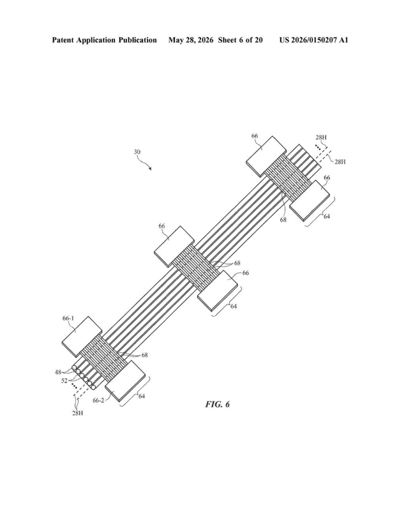
This patent describes a hinge built from interlocking "leaves" — thin, blade-like pieces that mesh together like fingers from two hands. Rollers help guide the motion, and shafts run through the leaves to anchor each rotation point. Some leaves have small gears so both sides of the display fold at exactly the same rate. Others have built-in stoppers so the device snaps to a fully open or fully closed position.
The result is a hinge that's meant to feel precise and controlled, rather than floppy or unpredictable — important when a delicate flexible display is riding right on top of it.
How the interdigitated leaves and rollers work together
The patent describes a foldable housing where two halves rotate relative to each other through a hinge with multiple axes of rotation — meaning the bending isn't happening around a single pivot point, but across several aligned shafts simultaneously. This distributed rotation is key to letting a flat flexible display bend without creasing or lifting off the hinge.
The core mechanical innovation is the interdigitated leaves — alternating blade-like structures from each housing half that mesh together. Each leaf has an opening through which a shaft passes, tying it to a specific axis of rotation. Think of it like the knuckles of a piano hinge, but multiplied and spread across several axes.
- Synchronization leaves include small gears that force both housing halves to rotate at equal angles — so one side can't fold faster or further than the other.
- Hard stop leaves include physical structures that prevent the device from opening past 180° or closing past 0° — giving the fold a definitive end-point feel.
- Vertical slot leaves with a shared pin can handle both jobs at once, simplifying the assembly.
Rollers coupled between the two halves reduce friction and help guide the flexible display smoothly over the hinge as it bends. The friction elements in the title refer to the controlled resistance built into the leaf system — enough drag to hold a position mid-fold, not so much that the device is hard to open.
What this means for a potential foldable iPhone or iPad
Foldable displays are only as good as their hinges. Samsung's Galaxy Z Fold line has iterated on hinge design for years, and the crease over the fold remains a top complaint. Apple entering this space — if it does — will be under enormous scrutiny to get the feel exactly right from day one. A multi-axis roller hinge with synchronized leaves and hard stops is exactly the kind of over-engineered precision mechanism Apple tends to prefer.
For you as a potential buyer, this kind of hinge engineering translates to a device that opens with a satisfying snap, stays put at whatever angle you set it, and doesn't develop wobble or looseness over thousands of cycles. It also suggests Apple is thinking carefully about protecting the flexible display from stress at the fold — a problem that has plagued every foldable phone on the market.
This is a genuinely detailed mechanical patent, not a vague placeholder. The specificity of the interdigitated leaf geometry, the dual-function vertical slot design, and the multi-shaft synchronization scheme all point to real engineering work, not concept sketching. Apple clearly has a team deep in foldable hinge R&D — whether or not a product ships anytime soon.
There are more where this came from
We read every patent application Big Tech publishes and send you the ones worth knowing. Plain English, free, every week.
The drawings
20 drawing sheets from US 2026/0150207 A1 · click any drawing to enlarge
What the drawings show
In Apple's own words, from the filing:
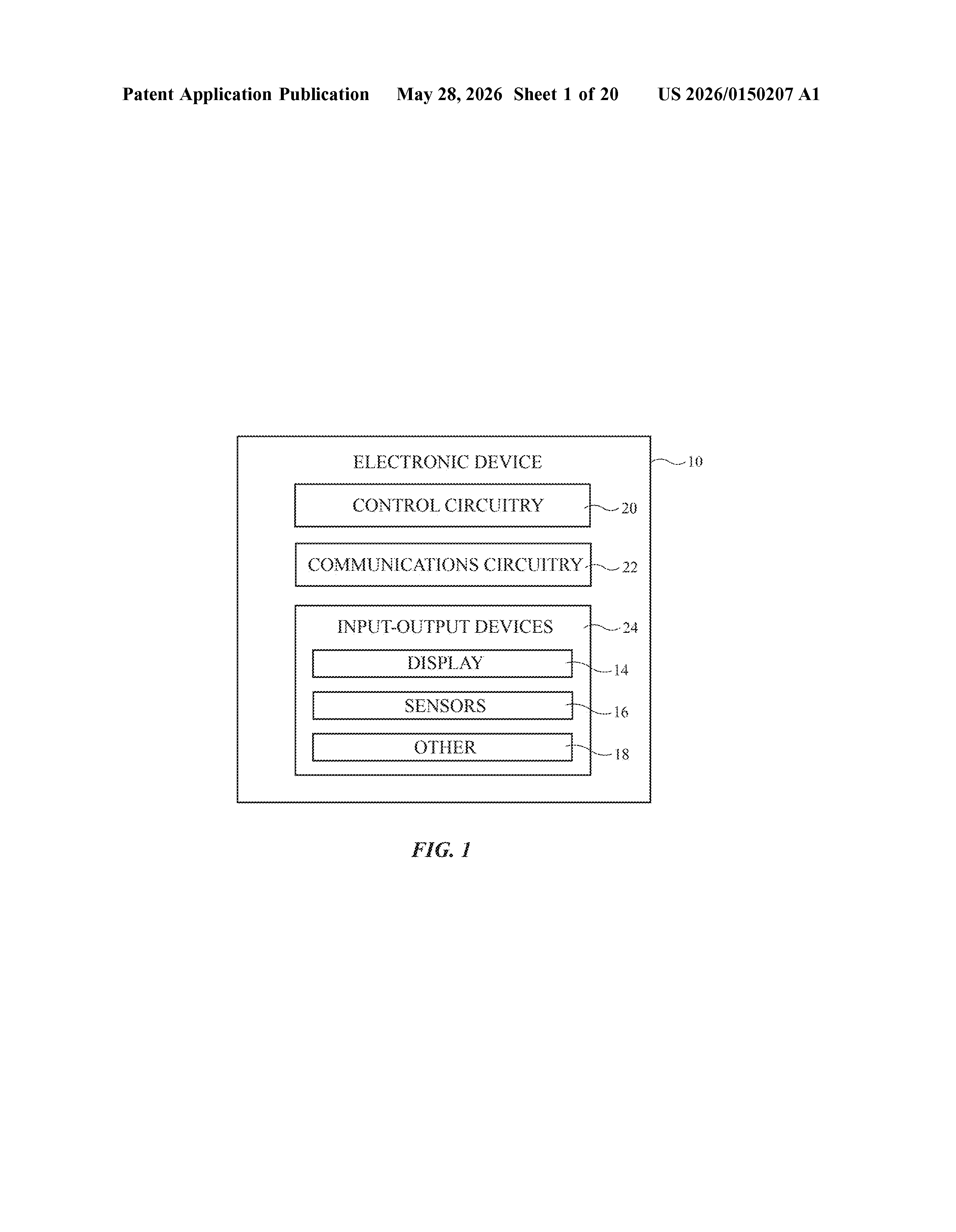
- FIG. 1 is a schematic diagram of an illustrative electronic device in accordance with some embodiments.
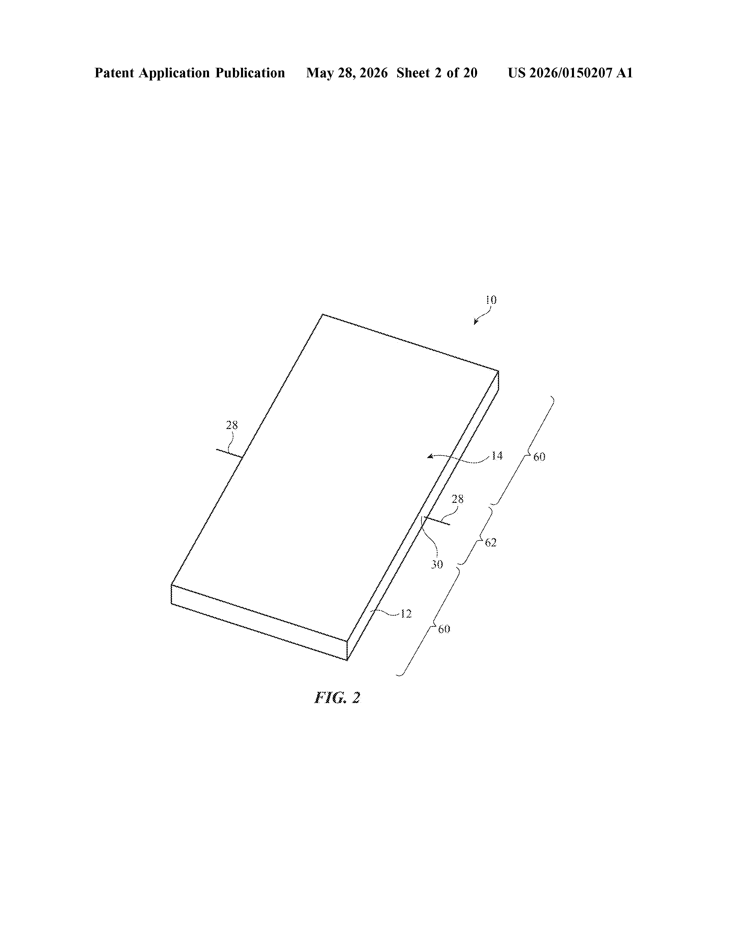
- FIG. 2 is a perspective view of an illustrative electronic device with a display in accordance with some embodiments.
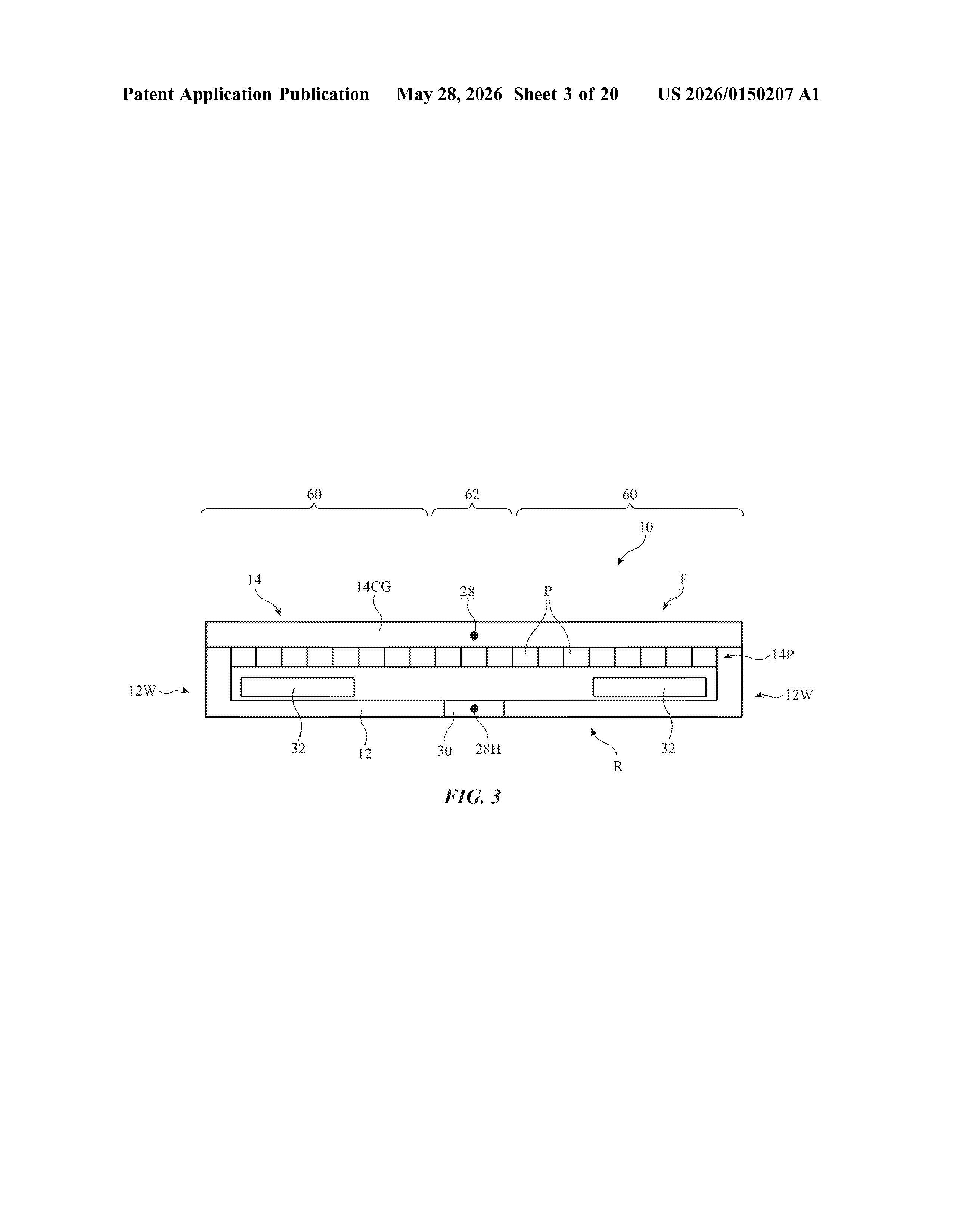
- FIG. 3 is a side view of an illustrative electronic device in accordance with some embodiments.
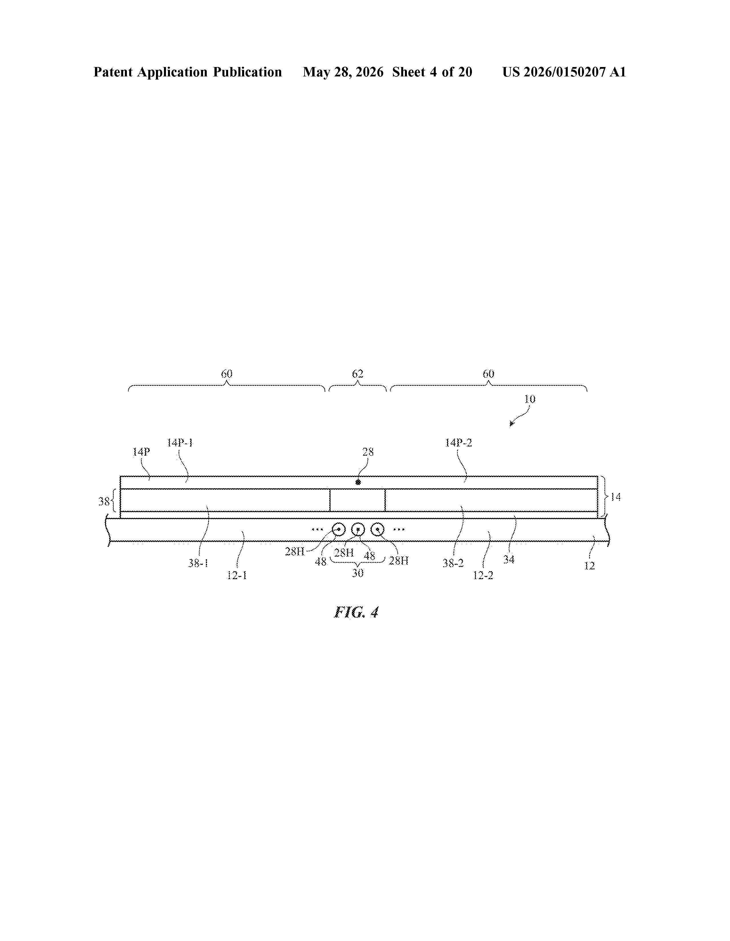
- FIG. 4 is a side view of an illustrative electronic device having a foldable housing and a foldable display in a flat state in accordance with some embodiments.
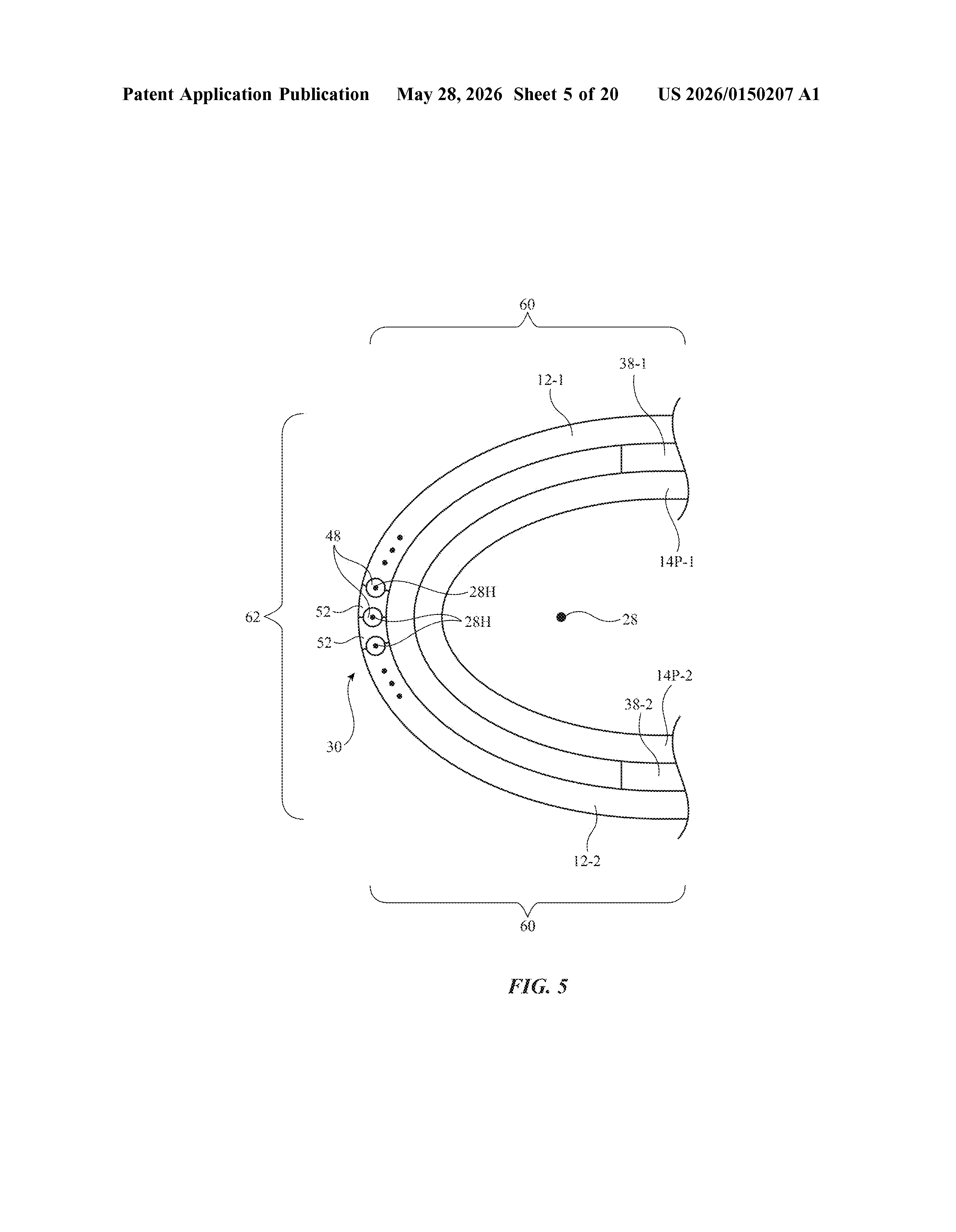
- FIG. 5 is a side view of the electronic device of FIG. 4 in a folded state in accordance with some embodiments.
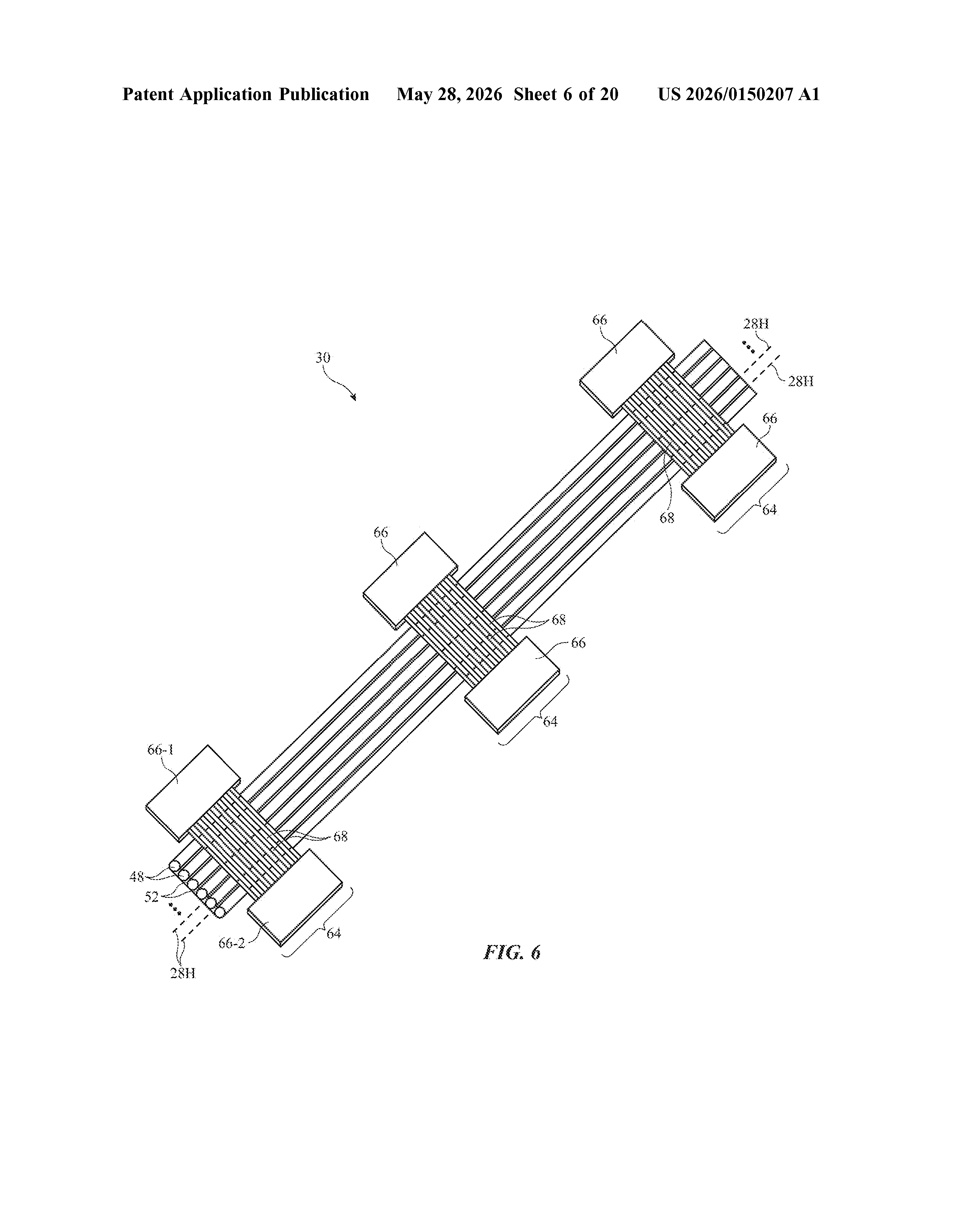
- FIG. 6 is a perspective view of an illustrative hinge assembly that includes parallel rollers coupled to hinge modules with interdigitated friction leaves in accordance with some embodiments.
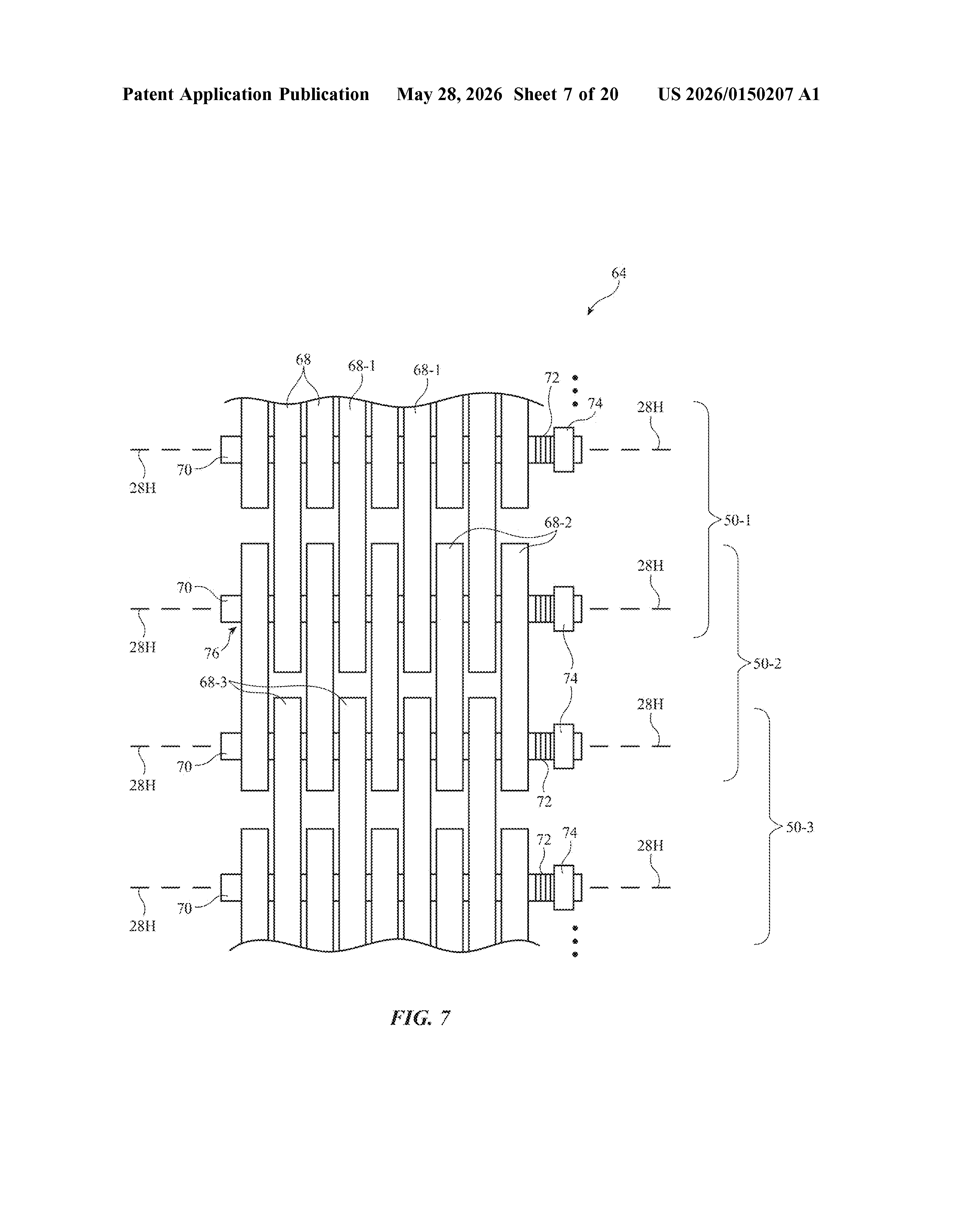
- FIG. 7 is a top view of an illustrative hinge module that may be used in the hinge assembly of FIG. 6 in accordance with some embodiments.
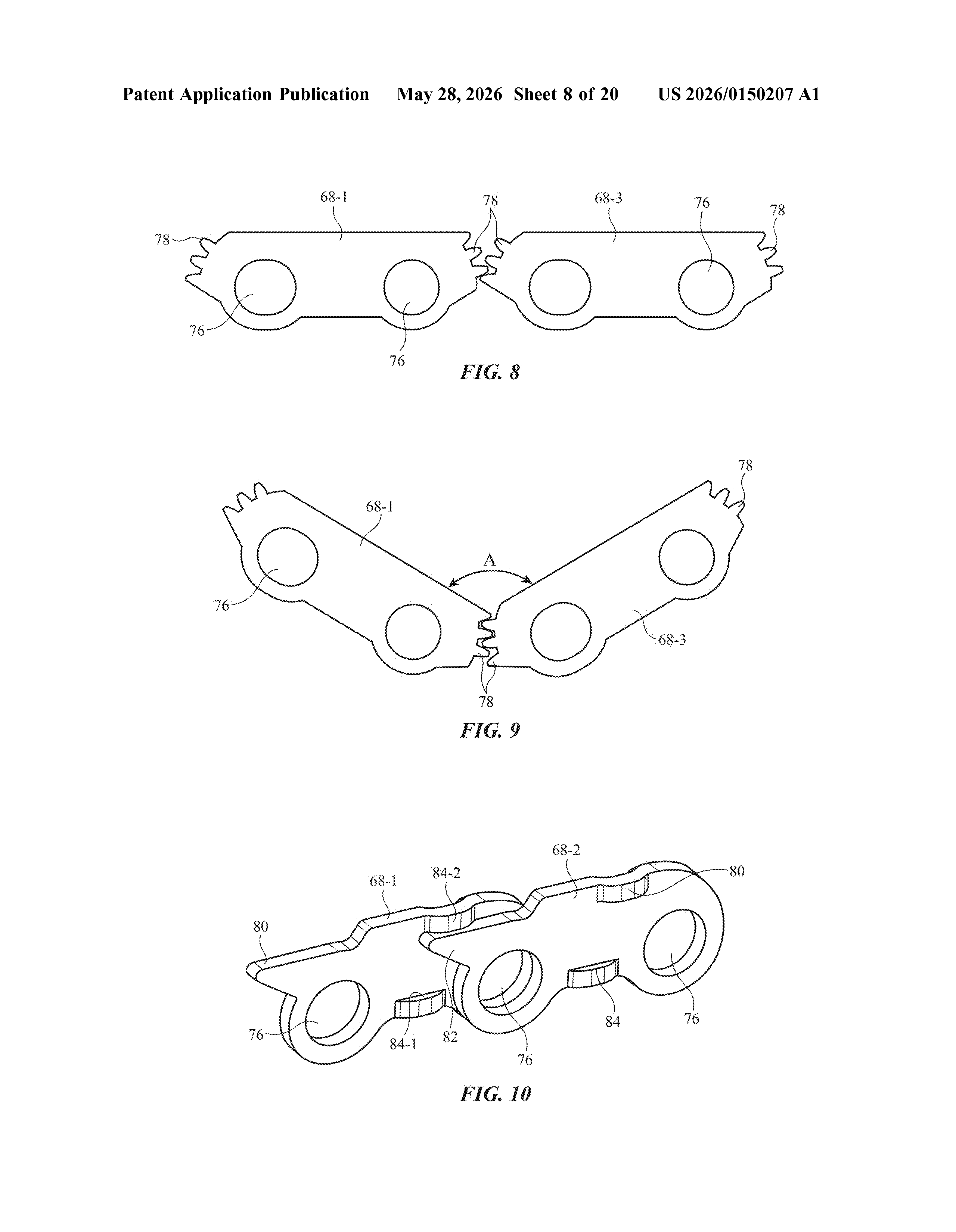
- FIGS. 8 and 9 are front views of an illustrative pair of friction leaves that may be used in the hinge modules of FIGS. 6 and 7 with gears for driving synchronous motion of first and second housing portions in accordance with some embodiments.
Show the other 15 descriptions
- FIG. 10 is a perspective view of an illustrative pair of friction leaves that may be used in the hinge modules of FIGS. 6 and 7 with hard stop structures for providing an open hard stop position and a closed hard stop position in accordance with some embodiments.
- FIGS. 11 and 12 are front views of an illustrative set of friction leaves that may be used in the hinge modules of FIGS. 6 and 7 with openings and vertical slots that receive pins for driving synchronous motion of first and second housing portions and for providing hard stops in the open and closed positions in accordance with some embodiments.
- FIG. 13 is an exploded perspective view of a hinge module that includes friction leaves of the type shown in FIGS. 11 and 12 in accordance with some embodiments.
- FIG. 14 is a front view of an illustrative friction leaf having an opening formed from one or more cantilevered arms and configured to receive a pin in accordance with some embodiments.
- FIG. 15 is an exploded perspective view of a hinge module that includes double-headed friction leaves for receiving shafts and pins as discussed in connection with FIGS. 11 and 12 in accordance with some embodiments.
- FIG. 16 is an exploded perspective view of an illustrative hinge module having friction reducing cams that load and unload friction leaves as the electronic device moves between folded and unfolded states in accordance with some embodiments.
- FIG. 17 is a side view of illustrative friction reducing cams of the type shown in FIG. 16 showing how the friction reducing cams are positioned when the electronic device is in a folded, fully closed state in accordance with some embodiments.
- FIG. 18 is a side view of illustrative friction reducing cams of the type shown in FIG. 16 showing how the friction reducing cams are positioned when the electronic device is in an unfolded, fully open state in accordance with some embodiments.
- FIG. 19 is a side view of a portion of an illustrative hinge module having friction reducing cams and a movable sleeve that is used to load and unload friction leaves as the electronic device moves between folded and unfolded states in accordance with some embodiments.
- FIG. 20 is a side view of illustrative friction reducing cams of the type shown in FIG. 19 showing how the friction reducing cams are positioned when the electronic device is in a folded, fully closed state in accordance with some embodiments.
- FIG. 21 is a side view of illustrative friction reducing cams of the type shown in FIG. 19 showing how the friction reducing cams are positioned when the electronic device is in an unfolded, fully open state in accordance with some embodiments.
- FIG. 22 is a side view of illustrative detent cams configured to produce an opening torque as the electronic device moves into an unfolded state in accordance with some embodiments.
- FIG. 23 is a side view of a portion of an illustrative hinge module having detent cams that produce opening torque and friction reducing cams that reduce a load on friction leaves as the device approaches an unfolded state in accordance with some embodiments.
- FIG. 24 is a side view of an illustrative friction leaf having a detent feature that produces an opening torque in accordance with some embodiments.
- FIG. 25 is a side view of illustrative friction leaves that include press fit holes for receiving timing pins in accordance with some embodiments.
Want this weekly breakdown for a company we don't cover? Patentlyze Pro →