
Bambu Lab
Bambu Lab · Hardware · Filed Jun 29, 2026 · USPTO published Nov 19, 2026 · This week's release
Bambu Lab Patents a Two-Material 3D Printer With a Lighter Moving Assembly
Most two-nozzle 3D printers bolt both filament-feeding motors onto the moving print head. This patent application leaves one of them off the head, so there is less weight to push around.
- Publication number
- US 2026/0364878 A1(US20260364878A1)
- Applicant
- SHENZHEN TUOZHU TECHNOLOGY CO., LTD.
- Filed · Published
- Jun 29, 2026 · Nov 19, 2026
- Inventors
- Li LIU, Zhihao DING, Zhao TONG, Xin LIU, Jiarong HUANG, Xuejian JIN
- Status when we published
- Waiting for an examiner
- Document
- 15 claims
- US classification
- 425/375
- Parent application
- Continuation of PCT/CN2025/112291 (filed Aug 1, 2025)(PCTCN2025112291)
What Bambu Lab's two-nozzle printer changes
Every time a 3D printer swings its print head across the bed, it has to drag along everything bolted to that head. Printers that can print in two materials or colors tend to pile on extra parts, and the filing says that added weight slows the head down and hurts its control accuracy.
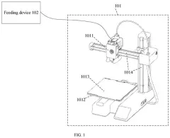
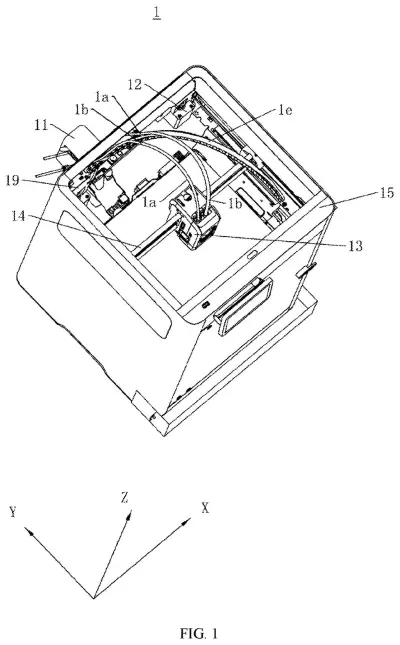
Bambu Lab's answer is to split the job. The head carries two nozzles, but only one of the two feeding motors (the small gadgets that push plastic thread toward the nozzle) rides along. The other sits on the outside of the printer's housing and pushes its thread down a thin tube.
The filing pairs them with some thought. A stiff plastic comes from the distant motor, while a soft, rubbery plastic comes from the motor right next to its nozzle, since stretchy thread is harder to control. The result is a lighter head that can move faster.
… the first extrusion assembly is spaced apart from the 3D printing head; the 3D printing head is slidably connected to the guide member, and the driving member is in transmission connection with the 3D printing head …
Translation: The main motor feeder is separated from the moving print head to reduce weight.
How a bump on the wall swaps the nozzles
The claimed printer has a rail or rod that the print head slides along, a drive that moves the head, and a connecting frame on the head holding two hot ends (the heated parts that melt plastic thread and squirt it out of a nozzle). One feeding assembly, a motor plus two wheels that pinch the thread and push it forward, is spaced apart from the head. The second feeding assembly sits on the head itself.
In the filing's example, hard plastic thread such as PLA or PETG goes through the remote feeder, and soft plastic such as TPU or TPE goes through the head-mounted one. The remote feeder is harder to control precisely, so the filing assigns it the support material, the scaffolding that gets snapped off the finished part. The other nozzle prints the main body.
The filing also describes several supporting details:
- A thinner tube for the remote thread, to keep it from wobbling and jamming over the long run.
- A ribbed inner wall in the soft-thread tube, to cut friction.
- A hot end that moves up and down so the idle nozzle sits higher and won't scrape the print.
- A passive lifting trick: the head bumps a hinged bar on the housing, and a lever, gear and rack raise or lower the nozzle with no extra motor.
- A detachable feeder with a heat-sinking motor against a metal housing.
When the driving member drives the 3D printing head, the first extrusion assembly does not need to move along with the 3D printing head on the guide member.
Translation: Keeping the heavy feeder stationary allows the print head to move much faster.
What a lighter print head means for printing
If you print with soft or multi-color materials, a lighter head is the whole point. Less weight on the head means it can accelerate and stop more quickly, and the filing says it also helps keep the head's movements accurate. Two nozzles also mean you don't have to flush leftover plastic every time you change material, which saves time and waste.
The design also keeps the feeder for fussy, bendy plastic right beside its nozzle, where the thread has a short, straight path. The rest of the thread travels through a tube from the outside of the machine. For hobbyists, that could mean faster multi-material prints without a bulky head, though the filing doesn't promise specific speeds.
Bambu Lab's second patent application we've tracked since November builds on our Bambu Lab coverage that began with a missing print plate detector.
Source: US 2026/0364878 A1 at the USPTO (PDF). Full patent text and figures are in the official publication.
Get our take in your Top Stories
Liked this breakdown? Add Patentlyze as a preferred source on Google, and our plain-English take shows up more often in your Top Stories the next time Bambu Lab patent news breaks.
Add Patentlyze on Google
One click.
There are more where this came from
We read the new patents from Big Tech, carmakers and more and send you the ones worth knowing. Plain English, free, every week.
The drawings · 25 sheets
25 drawing sheets from US 2026/0364878 A1 · click any drawing to enlarge


Show the other 17 sheets


More from Bambu Lab
All 2 Bambu Lab patents →More in Hardware
All 2,375 Hardware patents →
Qualcomm
Qualcomm Patents Earbuds That Let You Answer a Call With a Nod
Apple
Apple Patents a Folding Screen Hinge That Props Up the Display While You Type
OpenAI
A New OpenAI Patent Describes Earbuds That Pick Up Words You Only Mouth
Sony
No comments yet