Get the newsletter
Greenworks · Gear · Filed Jul 21, 2026 · USPTO published Nov 19, 2026 · This week's release

Greenworks Patents a Riding Mower With Motors Built Into Each Wheel and a Battery Mounted Below the Seat

Greenworks has filed a patent application for an electric riding mower that moves the motors into the wheels and drops the battery low beneath your seat. The aim is a machine that stays planted on a slope.
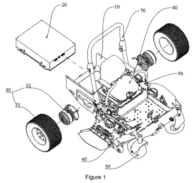
An electric riding lawn mower taken apart to show its frame, drive wheels, and main power pack. Drawing from patent filing US 2026/0363167 A1.
An electric riding lawn mower taken apart to show its frame, drive wheels, and main power pack.All 37 drawings ↓
Publication number
US 2026/0363167 A1(US20260363167A1)
Applicant
Greenworks (Jiangsu) Co., Ltd
Filed · Published
Jul 21, 2026 · Nov 19, 2026
Inventors
Qunli WEI, Dongdong SHI, Chen ZHU, Min DING, Chaoqun WANG, Fei ZHU, Jun FAN, Liang PENG
Status when we published
Waiting for an examiner
Document
20 claims
US classification
56/10.1
Parent application
Continuation of 18/536,143 (filed Dec 11, 2023)(18536143)

What Greenworks' wheel-motor mower actually does

You're on a riding mower, crossing a sloped backyard, and the whole machine feels top-heavy behind you. There is a reason for that: on many electric riding mowers, the heavy battery sits high and toward the back, right above the motor.

Greenworks's patent application rearranges the parts. Instead of one motor and a gearbox tucked inside the frame, each rear wheel gets its own hub motor, a motor built into the wheel and mounted outside the frame. That frees up room inside, so the battery can be lowered and stretched forward until it sits under your seat, between two long frame rails.

A lower battery means a lower center of gravity, the point where the machine's weight balances. The company says that makes the mower steadier when you drive and when you climb a hill.

From the filing · CLAIM 1
… the battery pack being positioned between the pair of longitudinal beams such that, in a projection onto a horizontal plane, at least a portion of the battery pack is located inward of a lateral edge of the seat along a width direction of the mower to lower a center of gravity of the mower.

Translation: The heavy battery sits low and centered between the frame rails to keep the mower stable on hills.

How the battery sits between the frame beams

The claims describe a riding mower with a frame, a seat, wheels and a battery pack mounted at least partly beneath the seat. The frame has two longitudinal beams (the long rails running front to back), and the battery sits between them. Seen from above, part of the battery falls inside the side edges of the seat, which the claim says lowers the mower's center of gravity (the point where its weight balances).

Other independent claims add a recessed compartment in the frame directly below the seat. The battery's own balance point sits lower than the axle line of a hub motor (an electric motor built into the wheel and mounted outside the frame), and the compartment is meant to offset the weight of those outside motors. Smaller claims cover two battery modules on either side of the center line, an airflow channel for cooling, a waterproof housing, and a battery that slides out through a rear or side opening.

The description puts numbers on it, all compared with a similar mower that uses one motor and a gearbox:

  • The battery space grows to 860 by 710 by 240 mm, about 40% longer, for roughly one-third more capacity.
  • The battery's balance point moves 135 mm forward and 170 mm lower.
  • The whole mower's center of gravity drops about 40 mm, and the power wire gets about 400 mm shorter.

The description also covers a cutting-deck cooling vent, a shielded braking resistor and an adjustable front blower, but the claims stick to the battery layout.

From the filing · THE ABSTRACT
The first walking wheel assembly and/or the second walking wheel assembly includes a main walking wheel and a hub motor, the main walking wheel is connected with the hub motor, and the hub motor is arranged outside a side of the vehicle frame.

Translation: Electric motors are built directly into the wheels instead of using a traditional transmission.

Why a lower battery matters on a slope

If this layout reaches a real mower, you would notice it on slopes, where a lower battery should feel more planted. The filing also lists everyday perks: no gear oil to change, a motor the company says costs one-third to one-half less than a gearbox setup, and a bigger battery for more capacity.

A patent application describes an idea, not a product, and this one names no model or launch date. The numbers come from Greenworks's own comparison with a similar gearbox mower. Still, the layout answers a plain question every electric riding mower has to settle: where to put a very heavy battery.

Source: US 2026/0363167 A1 at the USPTO (PDF). Full patent text and figures are in the official publication.

Get our take in your Top Stories

Liked this breakdown? Add Patentlyze as a preferred source on Google, and our plain-English take shows up more often in your Top Stories the next time Greenworks patent news breaks.

There are more where this came from

We read the new patents from Big Tech, carmakers and more and send you the ones worth knowing. Plain English, free, every week.

The drawings · 37 sheets

37 drawing sheets from US 2026/0363167 A1 · click any drawing to enlarge

Main mower parts including wheel motors and an underseat battery, drawing sheet 1 from US 2026/0363167 A1
Sheet 1 Main mower parts including wheel motors and an underseat battery
Where the battery pack sits beside rear drive wheels, drawing sheet 2 from US 2026/0363167 A1
Sheet 2 Where the battery pack sits beside rear drive wheels
Side and front views of the rear wheel motor unit, drawing sheet 3 from US 2026/0363167 A1
Sheet 3 Side and front views of the rear wheel motor unit
Wheel motor cross section and the twin-blade mowing deck, drawing sheet 4 from US 2026/0363167 A1
Sheet 4 Wheel motor cross section and the twin-blade mowing deck
Underside blade layout and the empty cutting deck shell, drawing sheet 5 from US 2026/0363167 A1
Sheet 5 Underside blade layout and the empty cutting deck shell
Inside the mower deck and blade drive motor, drawing sheet 6 from US 2026/0363167 A1
Sheet 6 Inside the mower deck and blade drive motor
Close-ups of the blade mount and internal motor seals, drawing sheet 7 from US 2026/0363167 A1
Sheet 7 Close-ups of the blade mount and internal motor seals
Assembled and exploded views of the electric blade motor stack, drawing sheet 8 from US 2026/0363167 A1
Sheet 8 Assembled and exploded views of the electric blade motor stack
Show the other 29 sheets
Three views of the lower cover enclosing the cutting motor, drawing sheet 9 from US 2026/0363167 A1
Sheet 9 Three views of the lower cover enclosing the cutting motor
Using a wrench to remove the mower blade, drawing sheet 10 from US 2026/0363167 A1
Sheet 10 Using a wrench to remove the mower blade
Where the cooling resistor fits under the mower frame, drawing sheet 11 from US 2026/0363167 A1
Sheet 11 Where the cooling resistor fits under the mower frame
Built and exploded views of the vented brake resistor pack, drawing sheet 12 from US 2026/0363167 A1
Sheet 12 Built and exploded views of the vented brake resistor pack
How outdoor airflow pulls heat away from the exposed resistor, drawing sheet 13 from US 2026/0363167 A1
Sheet 13 How outdoor airflow pulls heat away from the exposed resistor
Front-mounted leaf blower attachment with an aiming lever, drawing sheet 14 from US 2026/0363167 A1
Sheet 14 Front-mounted leaf blower attachment with an aiming lever
Exploded components linking the manual handle to the blower nozzle, drawing sheet 15 from US 2026/0363167 A1
Sheet 15 Exploded components linking the manual handle to the blower nozzle
Side view showing the nozzle adjustment lever in neutral position, drawing sheet 16 from US 2026/0363167 A1
Sheet 16 Side view showing the nozzle adjustment lever in neutral position
How the adjustment handle locks into the blower base, drawing sheet 17 from US 2026/0363167 A1
Sheet 17 How the adjustment handle locks into the blower base
Top view showing the lever locked in the center notch, drawing sheet 18 from US 2026/0363167 A1
Sheet 18 Top view showing the lever locked in the center notch
Pulling the handle sideways unlocks it from the teeth, drawing sheet 19 from US 2026/0363167 A1
Sheet 19 Pulling the handle sideways unlocks it from the teeth
Unlocked handle ready to shift into a new angle, drawing sheet 20 from US 2026/0363167 A1
Sheet 20 Unlocked handle ready to shift into a new angle
Pushing the lever forward to tilt the nozzle up, drawing sheet 21 from US 2026/0363167 A1
Sheet 21 Pushing the lever forward to tilt the nozzle up
Internal flap angling upward to redirect the airflow, drawing sheet 22 from US 2026/0363167 A1
Sheet 22 Internal flap angling upward to redirect the airflow
Pulling the lever backward to point the airflow down, drawing sheet 23 from US 2026/0363167 A1
Sheet 23 Pulling the lever backward to point the airflow down
Internal flap tilting downward to blow toward the ground, drawing sheet 24 from US 2026/0363167 A1
Sheet 24 Internal flap tilting downward to blow toward the ground
Riding mower carrying an adjustable front leaf blower attachment, drawing sheet 25 from US 2026/0363167 A1
Sheet 25 Riding mower carrying an adjustable front leaf blower attachment
Crank assembly used to steer the blower nozzle, drawing sheet 26 from US 2026/0363167 A1
Sheet 26 Crank assembly used to steer the blower nozzle
Connectors that link the nozzle to the air duct, drawing sheet 27 from US 2026/0363167 A1
Sheet 27 Connectors that link the nozzle to the air duct
Linkage rod and gears that turn the blower nozzle, drawing sheet 28 from US 2026/0363167 A1
Sheet 28 Linkage rod and gears that turn the blower nozzle
Disassembled drive linkage showing springs and universal joints, drawing sheet 29 from US 2026/0363167 A1
Sheet 29 Disassembled drive linkage showing springs and universal joints
Turning the crank aims the blower nozzle airflow, drawing sheet 30 from US 2026/0363167 A1
Sheet 30 Turning the crank aims the blower nozzle airflow
Mower fitted with the crank-adjusted front leaf blower, drawing sheet 31 from US 2026/0363167 A1
Sheet 31 Mower fitted with the crank-adjusted front leaf blower
Motorized version of the blower that aims air electronically, drawing sheet 32 from US 2026/0363167 A1
Sheet 32 Motorized version of the blower that aims air electronically
Parts of a motorized leaf blower attachment taken apart, drawing sheet 33 from US 2026/0363167 A1
Sheet 33 Parts of a motorized leaf blower attachment taken apart
Motor assembly that steers the blower's nozzle, drawing sheet 34 from US 2026/0363167 A1
Sheet 34 Motor assembly that steers the blower's nozzle
Internal gears that swivel the curved air chute, drawing sheet 35 from US 2026/0363167 A1
Sheet 35 Internal gears that swivel the curved air chute
Electric steering motor and the circuitry that powers it, drawing sheet 36 from US 2026/0363167 A1
Sheet 36 Electric steering motor and the circuitry that powers it
Riding mower carrying the motorized leaf blower up front, drawing sheet 37 from US 2026/0363167 A1
Sheet 37 Riding mower carrying the motorized leaf blower up front
Patent filing page

Reader comments

No comments yet

Start the discussion

Real name or a handle, either is fine. Comments are read by a person before they appear, so allow a little time. Keep it about the filing.