
Hilti
Makita · Gear · Filed Jul 22, 2026 · USPTO published Nov 19, 2026 · This week's release
Makita Files Patent for a Demolition Hammer With Handles That Absorb Vibration
Makita has filed a patent for a big cordless demolition hammer where your hands never touch the part that is pounding. The handles, battery and electronics ride on a separate frame that floats on springs.
- Publication number
- US 2026/0364763 A1(US20260364763A1)
- Applicant
- MAKITA CORPORATION
- Filed · Published
- Jul 22, 2026 · Nov 19, 2026
- Inventors
- Kiyonobu YOSHIKANE, Masanori FURUSAWA, Hideki TSUJI
- Status when we published
- Waiting for an examiner
- Document
- 19 claims
- US classification
- 173/117
- Parent application
- Continuation of 17/842,014 (filed Jun 16, 2022)(17842014)
What Makita's floating-handle hammer actually does
Every time someone leans on a demolition hammer to break up a slab of concrete, the tool shakes its way up into their wrists, elbows and shoulders. Big hammers are heavy, powerful and rough on the people who run them all day.
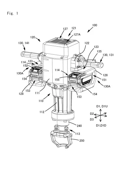
Makita's patent splits the tool into two parts. The lower body holds the motor and the pounding machinery. The upper frame holds the two handles, the control electronics and the battery sockets. The two halves are joined by springs, so the shaking stays mostly in the lower body while you hold the calm half.
The filing also adds guide rails so the two halves slide straight up and down without wobbling, plus a rubber stop so they never slam together. It even uses that same sliding motion as a signal: push down on the handles and the hammer wakes up from a quiet idle.
… a first elastic member disposed between the first housing and the second housing, wherein the drive mechanism and the motor are disposed at the first housing, the pair of handles are disposed at the second housing, the second housing is, together with the pair of handles, movable relative to the first housing via the first elastic member …
Translation: Springy parts separate the vibrating motor from the handles so your hands do not shake.
How the two-part housing soaks up the pounding
The first claim covers a hammer built from two housings. The first housing carries the motor and the drive mechanism (the parts that turn spinning into hard up-and-down blows). The second housing carries both handles. A spring sits between them, so the handles and the second housing can move up and down relative to the first.
The key detail is how that sliding is kept tidy. Slide guide members (rails and sleeves that keep two parts moving in one straight line) sit at several heights along the tool. The filing describes one set near the handles, with a metal pipe sliding inside a forked resin piece, and another set lower down, with a ridge fitting into a groove with a bent sheet-metal liner.
Other claims add pieces that work together:
- A stopper that limits how far the halves can travel (10 mm in the example), so they never knock together.
- A cushion that softens the move before it hits the stopper.
- A second, softer spring that handles the first 2 mm of push, while the stiff main spring handles the vibration.
- A battery socket and guard on the handle-side half.
The description says the soft spring doubles as a trigger. A magnetic sensor notices when you push, and the motor speeds up from a low idle to full power.
Why a calmer handle matters on a big cordless hammer
If you do demolition or road work, or you rent these tools, the practical gain is less shaking in your hands and arms. The filing says the handle-side half also protects the control board and the battery from the pounding, which could mean longer-lasting tools that spend less time in repair.
It also fits where cordless tools are heading. The description says batteries keep getting bigger and heavier as hammers chase the power of corded ones. Moving the battery onto the calm half of the tool is a sensible way to carry that extra weight. This is a patent application, not a product, and the filing names no model.
Source: US 2026/0364763 A1 at the USPTO (PDF). Full patent text and figures are in the official publication.
Get our take in your Top Stories
Liked this breakdown? Add Patentlyze as a preferred source on Google, and our plain-English take shows up more often in your Top Stories the next time Makita patent news breaks.
Add Patentlyze on Google
One click.
There are more where this came from
We read the new patents from Big Tech, carmakers and more and send you the ones worth knowing. Plain English, free, every week.
The drawings · 22 sheets
22 drawing sheets from US 2026/0364763 A1 · click any drawing to enlarge


Show the other 14 sheets


No comments yet