
Samsung Patents a Safer Way for Chargers to Detect Connected Devices
Every time you plug a phone into a charger, the charger has to figure out something is there. Samsung's new patent focuses on making that detection safer by electrically separating the sensing circuit from the high-voltage power path.
What Samsung's charger detection circuit actually does
A wall charger sits on a desk, waiting. The moment you plug your phone into it, the charger needs to know a device just arrived so it can start sending power safely. That handshake sounds simple, but the electronics doing it live dangerously close to high voltages.
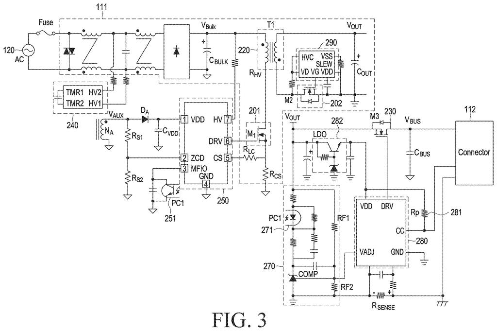
Samsung's patent describes a detection circuit that uses a small resistor to sense whether your device is connected. On each side of that resistor sits a capacitor, acting as an electrical barrier. Those barriers keep the low-voltage sensing side of the circuit from touching the high-voltage side that actually drives power, which reduces the risk of a fault crossing over.
When you plug in, a signal travels through the second capacitor to a chip called the PWM controller (think of it as the charger's throttle). That chip then decides how much power to send. When you unplug, the signal disappears and the charger knows to stop.
… a resistor configured to detect whether the external device is connected through the connector; a first circuit electrically connected to a first end of the resistor to supply a bias voltage to the resistor based on the power provided from the external power source; …
Translation: A resistor and circuit work together to sense when something is plugged into the charger.
How the two capacitors isolate and signal the PWM chip
The patent describes a power adapter architecture built around safe device detection. Here is how the key pieces fit together:
- Power conversion circuit: Takes AC from the wall and converts it to the DC your device needs, using a transformer (a component that steps voltage up or down).
- Detection resistor: A small component that carries a tiny bias voltage. When a device is plugged in, the electrical path changes, and that change is the signal the charger reads.
- First circuit (bias side): Connected to one end of the resistor, it supplies the bias voltage. It contains a first capacitor that provides galvanic isolation (meaning no direct electrical path) and distributes voltage safely across both ends of the circuit.
- Second circuit (signal side): Connected to the other end of the resistor, it reads the change caused by a connected device and passes that information to the PWM controller. A second capacitor provides the same isolation function on this side.
- PWM circuit: Short for pulse width modulation, this is the controller that regulates power delivery by rapidly switching a transistor on and off. The ratio of on-time to off-time controls how much energy moves through the transformer.
The two-capacitor arrangement is the core claim. By isolating both ends of the sensing resistor from the main power path, the design keeps detection signals from accidentally interacting with the transformer's primary coil, where voltages are much higher.
… wherein the first circuit includes a first capacitor for capacitor isolation and voltage distribution at both ends of the first circuit, and the second circuit includes a second capacitor for capacitor isolation and voltage distribution at both ends of the second circuit.
Translation: Special capacitors help manage electrical voltage and safely isolate the circuits.
What this means for charger safety and design
Charger safety is a largely invisible engineering problem. A detection fault that lets high-voltage signals bleed into low-voltage sensing circuitry can cause component damage or, in worse cases, create a safety hazard. Samsung's approach puts a deliberate electrical barrier on both sides of the sensing element, which is a more symmetric defense than putting isolation on just one side.
This is squarely an internal design patent, aimed at engineers specifying charger ICs and adapter boards rather than at any consumer product feature you would notice. Still, it reflects the kind of methodical power-circuit work that shows up across new Big Tech patents in the charging and power-delivery space as companies push adapters toward higher wattages where safety margins matter more.
High-voltage isolation failures in charger circuits are a known failure mode, and the cost of getting it wrong runs from a fried device to a fire hazard. Samsung's two-capacitor symmetry is a tidy engineering answer to that risk. Whether it meaningfully improves on existing isolation techniques or mainly varies the design will depend on prior art the patent office has yet to weigh, but the underlying problem is exactly the sort that justifies careful, quiet circuit work.
There are more where this came from
We read every patent application Big Tech publishes and send you the ones worth knowing. Plain English, free, every week.
The drawings
10 drawing sheets from US 2026/0238136 A1 · click any drawing to enlarge


Want this weekly breakdown for a company we don't cover? Patentlyze Pro →
Be the first to weigh in