
Snap
Snap · AR / VR · Filed May 6, 2026 · USPTO published Nov 19, 2026 · This week's release
Snap Patents Smart Glasses That Use the Battery as Part of the Antenna
Snap's smart glasses patent turns the battery behind your ear into part of the antenna, so a radio fits where there is hardly room for one. The battery's metal case does double duty.
- Publication number
- US 2026/0369884 A1(US20260369884A1)
- Applicant
- Snap Inc.
- Filed · Published
- May 6, 2026 · Nov 19, 2026
- Inventors
- Catlynn Duc Zarquan Nguyen, Ugur Olgun, Brandon R Collins-Smoot
- Status when we published
- Waiting for an examiner
- Document
- 20 claims
- US classification
- 343/718
- Parent application
- Claims priority from a provisional application 63805476 (filed May 14, 2025)
What Snap's battery antenna actually does
Every time your smart glasses reconnect to your phone or your home Wi-Fi, a tiny antenna has to catch the signal. And a pair of glasses has almost no spare room to hide one. Snap's patent application describes a workaround: let the battery help.
The battery sits at the back of each arm, behind your ear, and its case is metal. Snap's design runs a thin strip of metal around that battery and uses the case as part of the antenna. The strip works two ways at once, like a ring around the battery and a short branch sticking out of it. Each handles different radio bands, so one small part can cover Wi-Fi, Bluetooth and more.
Putting it at the back also keeps the radio away from the front of the frame, where the cameras, lenses and sensors live.
… a hybrid antenna assembly electrically coupled to the battery assembly, the hybrid antenna assembly having a conductive trace with a first portion forming a loop antenna section and a second portion forming a dipole antenna section …
Translation: The glasses use a special antenna connected to the battery that combines two different signal receiver designs into one wire.
How one metal strip acts as loop and branch
The core is one conductive trace (a thin strip of metal printed on a plastic holder) that wraps around at least two sides of a battery sitting behind the wearer's ear. One part of the trace, together with the battery's metal case, forms a loop antenna (a ring-shaped antenna). A second part branches off at a tap point and forms a dipole antenna (a straight, rod-style antenna).
- Lengths set the frequency. Segments labeled L1, L2 and L3 decide which radio bands the antenna works best on.
- Gaps set the bandwidth. The spacing between the loop and the battery, and between the loop and the branch, controls how wide a slice of frequencies it covers.
- An extra branch adds a band. A fourth segment (L4) off a second tap point can add another band, higher or lower.
The trace is tied to the battery case with a spring contact or a screw, so the case acts as the loop's return path and the branch's negative pole. A low pass filter (a circuit that blocks high-frequency noise) keeps the antenna isolated from the processor and displays. In the example, the transceiver sits on one side of the battery and the chipset on the other.
The filing's test chart shows efficient operation near 2.4 to 2.5 GHz from the branch and across 5 to 7 GHz from the loop, covering Wi-Fi 6E's three bands.
What this means for thinner AR glasses
Smart glasses have to pack a battery, cameras, displays and several radios into something that still looks and feels like glasses. Every millimeter given to an antenna is taken from something else. Reusing the battery case, which has to be there anyway, is a way to get wireless range without adding bulk.
The filing also explains why the antenna moved. An earlier hybrid design put it in the front frame, where it could clash with the display parts and weaken the frame that keeps the displays lined up. Behind your ear, the antenna leaves the front of the glasses to the cameras and lenses. The filing says the same layout could also work in phones, tablets and even cars.
Source: US 2026/0369884 A1 at the USPTO (PDF). Full patent text and figures are in the official publication.
Get our take in your Top Stories
Liked this breakdown? Add Patentlyze as a preferred source on Google, and our plain-English take shows up more often in your Top Stories the next time Snap patent news breaks.
Add Patentlyze on Google
One click.
There are more where this came from
We read the new patents from Big Tech, carmakers and more and send you the ones worth knowing. Plain English, free, every week.
The drawings · 15 sheets
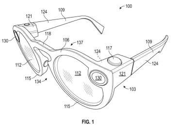
15 drawing sheets from US 2026/0369884 A1 · click any drawing to enlarge


Show the other 7 sheets


More from Snap
All 5 Snap patents →

More in AR / VR
All 718 AR / VR patents →
Apple
Apple Files Patent for Headset Labels That Turn to Face You as You Walk
Meta
Meta Patents a Fix for Washed-Out Blacks in Headset Displays
Meta
Meta Files Patent for a Headset That Shuts Down Safely When Its Cable Is Pulled
Sony
No comments yet