
A New Apple Patent Has Headset Lenses Slide Themselves to Fit Your Eyes
Every headset has to match the gap between its two lenses to the gap between your eyes. This Apple patent application hands that job to cameras and small motors, so you never touch a dial.
What Apple's self-adjusting headset lenses do
A person lifts a headset onto their face and the picture looks slightly off. They reach up, turn a knob or slide a lever, and nudge the lenses sideways until the blur fades.
That knob exists because everyone's eyes sit a different distance apart, a measurement called interpupillary distance. If the lenses don't line up with your pupils, the image can look fuzzy or tire your eyes.
Apple's patent application describes a headset that does this for you. Small cameras look at your eyes, the device works out the right spacing, and motors slide the two lens modules into place. The filing says this can happen while you're using it, with no input from you, and it can start the moment the headset detects it's on your head.
… automatically move the first optical module and the second optical module relative to the housing to positions corresponding to the target interpupillary distance.
Translation: The headset shifts the lenses on its own to match the exact distance between your eyes.
How the cameras and motors set the lens gap
The claims cover a head-mounted device with a housing and two optical modules (each one is a display plus the lens you look through). An adjustment assembly figures out a target interpupillary distance, meaning the ideal gap between the two modules, from sensor signals. It then moves both modules to match, without the wearer doing anything.
The sensors are mostly user-facing cameras that photograph one or both eyes. To see well in a dark headset, infrared emitters (LEDs that give off light you can't see) shine toward your eyes, and the cameras read the reflections. The filing describes LEDs arranged in a ring around the lens axis. The device can then spot where your pupils are, or how far apart they sit.
The filing also describes:
- Wear detection: the adjustment can start when cameras notice the headset is on your face.
- Ongoing changes: the spacing can keep adjusting if your detected eye characteristics change during use.
- Saved profiles: the device can look up a stored profile, built partly from a biometric ID of the wearer (for example an iris scan).
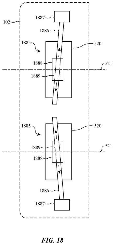
In the description, motors move the modules along support rods, and the front-facing cameras ride along with them, so the camera view matches your own eye spacing.
… an interpupillary distance adjustment assembly configured to determine a target interpupillary distance based on signals from one or more sensors …
Translation: Built in sensors figure out how far apart your eyes are so the lenses can align correctly.
Why a headset that fits itself matters to you
If you've ever fiddled with binoculars or a VR headset to get a sharp image, you know that setup friction is annoying. A headset that sets its own lens gap could make putting it on feel closer to putting on glasses. It could also help when someone else borrows the device, because the lenses would move to fit each new face.
The filing also ties the lens spacing to the front-facing cameras that show you the room around you. Because those cameras move with the lenses, the video you see is captured at your own eye spacing, which the filing says makes the 3D view more accurate. Auto-adjustment is a fit feature, but it feeds directly into how natural the headset's picture looks.
Apple has filed its 124th application we've tracked in our AR glasses watch since May, building on work like gaze-sharpened graphics and resizing floating surfaces.
The problem here is small but constant. Eye spacing differs from person to person, and a headset that misses it can give you blur and eye strain. That is a real comfort issue for a device you strap to your face for an hour at a time, and a motorized fix is a proportionate answer to it.
The approach also fits the hardware. The cameras that watch your eyes are already in the headset for other jobs, such as identifying you and tracking where you look, so using them to set the lens gap adds a purpose rather than a new part.
This is a continuation of earlier filings, and the claims are broad: sensors, a target distance, motors. Expect the real story to be in how fast and it works, which the patent does not say. As a convenience feature it looks sensible, and a mainstream user probably wouldn't notice it unless it failed.
Get our take in your Top Stories
Liked this breakdown? Add Patentlyze as a preferred source on Google, and our plain-English take shows up more often in your Top Stories the next time Apple patent news breaks.
There are more where this came from
We read every patent application Big Tech publishes and send you the ones worth knowing. Plain English, free, every week.
The drawings
16 drawing sheets from US 2026/0349259 A1 · click any drawing to enlarge


Show the other 8 sheets


Want this weekly breakdown for a company we don't cover? Patentlyze Pro →
Be the first to weigh in