
Apple
Apple · Cell phone · Filed Jul 22, 2026 · USPTO published Nov 19, 2026 · This week's release
Apple Files Patent for a Phone Built in Two Halves That Snap Together
Build the phone as two finished halves, tilt the screen half into the body like closing a lid, and let small metal springs click it into place. This Apple patent family reaches back to 2008, and it is still adding claims.
- Publication number
- US 2026/0370249 A1(US20260370249A1)
- Applicant
- Apple Inc.
- Filed · Published
- Jul 22, 2026 · Nov 19, 2026
- Inventors
- Erik L. Wang, Phillip Michael Hobson, Kenneth A. Jenks, Adam D. Mittleman, Bartley K. Andre, Daniel J. Coster, Daniele De Iuliis, Richard P. Howarth, Jonathan P. Ive, Steven P. Jobs, Duncan Robert Kerr, Shin Nishibori, Matthew Dean Rohrbach, Douglas B. Satzger, Calvin Q. Seid, Christopher J. Stringer, Eugene Anthony Whang, Rico L. Zorkendorfer
- Status when we published
- Waiting for an examiner
- Document
- 20 claims
- US classification
- 455/566
- Parent application
- Continuation of 19/022,892 (filed Jan 15, 2025)(19022892)
What Apple's two-piece phone body actually is
Ever tried to open up a gadget to fix it and ended up snapping a plastic tab or cracking the screen? Phones are packed so tightly that taking one apart, or putting one together on a factory line, is easy to get wrong.
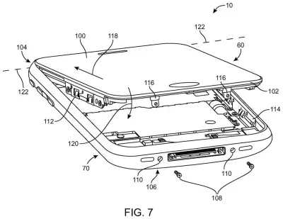
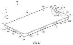
Apple's patent describes building the device as two finished halves. The top half holds the screen, the touch layer and the cover glass. The bottom half holds the plastic body, the circuit boards and the battery. Workers hook one end of the top half into the bottom, then tilt it down like closing a lid, and small metal springs click into matching clips.
Because nothing is glued or bent for good, a few screws come out and the halves separate for repair. Numbers next to each connection, plus instructions etched inside the case, tell workers what to plug in and in what order.
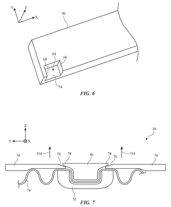
Engagement members may be connected to the first and second parts. The engagement members may be formed from metal clips with holes and springs with flexible spring prongs that mate with the holes in the clips.
Translation: Springs and metal clips snap the two halves together.
How the screen half tilts into the body
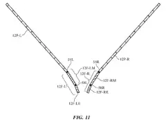
The filing splits a handheld device into a tilt assembly (the screen half) and a housing assembly (the body half). Each half can be built and tested on its own. If one fails a test, it can be fixed or thrown out without scrapping the whole phone.
The screen half has a frame made of metal struts (thin metal ribs) with plastic molded over them, a process called overmolding. That molded plastic forms a ledge, or shelf, that the cover glass rests on. The claims center on this plastic shelf, which sits parallel to the glass and can wrap around its edges. The filing also describes a softer gasket (a thin cushion of urethane or silicone) between the glass and the surrounding trim, so the glass doesn't get scratched.
To hold the halves together, the patent describes:
- Metal clips welded to the frame struts, each with holes cut into it.
- Metal springs welded to the trim ring on the body, with flexible prongs that poke into those holes.
- Retention clips and screws at one end for a firmer lock.
The clips and springs are thin stainless steel, about 0.2 mm thick. The angled, curved shapes forgive small errors, such as a weld that landed slightly off. The claims also cover an OLED screen across most of the front face, a touch sensor, and a cellular antenna that can use a metal part of the housing.
Why repairable phone housings matter to you
If you have ever paid for a phone repair, or wondered why some devices are nearly impossible to open, this is the territory. A phone that comes apart without bending or breaking its own parts is easier to fix and wastes less when a factory test finds a defect. The filing says so directly, citing less waste during rework and repair.
There is also a plain manufacturing benefit. Numbered connectors and etched instructions are meant to help unskilled workers assemble a device correctly, and to be followed in reverse for disassembly. That matters most to the people building phones at huge volume, though you could feel it in repair prices and in how often a screen swap goes wrong.
That makes this Apple's 12th filing we've tracked since May in the foldable phone race, following applications like a bending screen frame and a typing prop hinge.
Source: US 2026/0370249 A1 at the USPTO (PDF). Full patent text and figures are in the official publication.
Get our take in your Top Stories
Liked this breakdown? Add Patentlyze as a preferred source on Google, and our plain-English take shows up more often in your Top Stories the next time Apple patent news breaks.
Add Patentlyze on Google
One click.
There are more where this came from
We read every patent application Big Tech publishes and send you the ones worth knowing. Plain English, free, every week.
The drawings · 28 sheets
28 drawing sheets from US 2026/0370249 A1 · click any drawing to enlarge


Show the other 20 sheets


More from Apple
All 748 Apple patents →
More in Cell phone
All 494 Cell phone patents →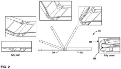
Google
Google Files Patent for a Foldable Screen Hinge Built Around Magnets
Samsung
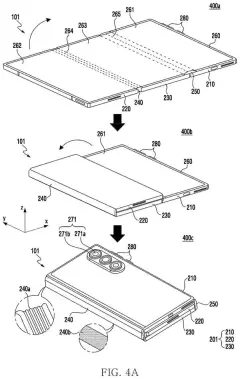
Samsung Files Patent for a Phone That Folds Twice and Still Works Closed
Samsung
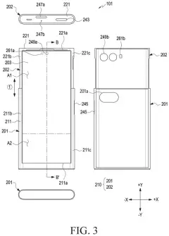
Samsung Files Patent to Keep a Slide-Out Phone Screen From Bulging at the Bend
Samsung
No comments yet