
Lutron
Lutron · Gear · Filed Jul 24, 2026 · USPTO published Nov 19, 2026 · This week's release
Lutron Patents a Clip-On Frame That Turns Old Wall Switches Into Smart Controls
You want smart lighting control, but your wall has a plain old toggle switch and you don't want to hire an electrician. Lutron's new patent covers a mounting frame that snaps over your existing switch, keeps it locked in the "on" position, and hands wireless control over to a touch panel sitting right on top.
- Publication number
- US 2026/0369484 A1(US20260369484A1)
- Applicant
- Lutron Technology Company LLC
- Filed · Published
- Jul 24, 2026 · Nov 19, 2026
- Inventors
- Chris Dimberg, Jason C. Killo, Brad Michael Kreschollek, Matthew Philip McDonald
- Status when we published
- Waiting for an examiner
- Document
- 20 claims
- US classification
- 307/140
- Parent application
- Continuation of 19/029,749 (filed Jan 17, 2025)(19029749)
What Lutron's no-wiring switch retrofit actually does
A plain toggle switch sits in the wall of a rented apartment or older home. The tenant wants smart lighting but cannot rewire anything. That gap is exactly what this patent addresses.
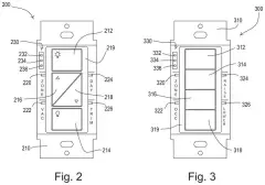
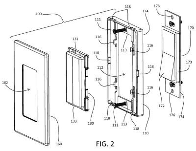
Lutron's system works by placing a plastic adapter frame directly over the existing switch. The frame screws into the same holes the old faceplate used, so there is no new wiring at all. A battery-powered touch panel then clips onto the front of the frame, and a faceplate snaps around it. The whole assembly sends wireless commands to a smart dimmer or smart bulb elsewhere on the circuit.
The filing also covers a two-switch wall plate. If your wall has two switches side by side, the same adapter bridges both. Special U-shaped brackets flip between two orientations to handle the fact that one switch may sit deeper in the wall than the other, letting you pull it forward until it lines up flush with the new faceplate.
an adapter that defines a first opening and a second opening that extend therethrough, wherein the adapter is configured to be attached to a first yoke of the mechanical switch, and wherein the adapter is configured to be attached to a second yoke of the electrical device mounted adjacent to the mechanical switch in the multi-gang wallbox …
Translation: The plastic frame fastens securely to the metal mounting brackets of your existing switches.
How the reversible brackets adjust for different switch depths
The core of the patent is a mounting frame assembly made up of an adapter plate and one or more reversible attachment brackets.
The adapter defines two openings: one that fits around the existing switch's bezel and actuator, and a second that accommodates the neighboring electrical device (a second switch or outlet) in the same multi-gang wallbox. The adapter attaches to the metal yoke (the mounting bracket already bolted to the wallbox) using the same screw holes the old decorative faceplate used.
The reversible brackets are U-shaped clips, each with a flat plate and two legs. Each bracket can snap into the adapter in either of two orientations:
- First orientation: the plate sits close to the wall surface, letting the bracket grip a switch yoke that sits at normal depth.
- Second orientation: the plate sits further forward, accommodating a switch or outlet whose yoke is recessed deeper in the box.
For a recessed neighbor device, the installer loosens the screws holding its yoke to the wallbox, then tightens the adapter's screws against that yoke. The yoke gets pulled forward until the switch face is flush with the new faceplate. The control unit itself snaps onto the brackets via snap-fit connectors, so no tools are needed to swap it out. A capacitive touch strip on the control unit handles gestures (tap, swipe, two-finger pinch) and sends radio-frequency commands to a separate smart dimmer or smart bulb.
The second electrical device may be recessed with respect to the remote control device and may be brought forward towards a front surface of the adapter by loosening a first set of screws that attach a yoke of the second electrical device to the multi-gang wallbox, and tightening a second set of screws that attach the adapter to the yoke of the second electrical device.
Translation: Adjustable screws let you pull nearby sunken outlets forward so they sit flush with the new cover plate.
What this means for renters and smart-home upgraders
Millions of homes still have mechanical toggle or paddle switches, and upgrading them usually means hiring an electrician to safely disconnect live wiring. For renters, that is often simply not allowed. For homeowners who already have smart bulbs in their fixtures, flipping the existing wall switch cuts power entirely, which breaks the wireless connection those bulbs depend on. Lutron keeps filing on wiring-free retrofit control, and this patent's specific answer is to lock the original switch in the "on" position and place a wireless controller over it, so the bulbs stay powered and controllable at all times.
The two-gang version matters because real walls rarely have just one switch. A retrofit that only handles single-gang boxes forces homeowners to leave the adjacent switch looking mismatched. The adjustable-depth brackets solve a fiddly installation problem: wallbox depths vary, and without some way to pull a recessed switch forward, the neighbor device ends up sitting behind the new faceplate's surface, looking sunken and unprofessional.
Lutron's second home tech filing we've tracked since November follows their wall keypad application.
Source: US 2026/0369484 A1 at the USPTO (PDF). Full patent text and figures are in the official publication.
Get our take in your Top Stories
Liked this breakdown? Add Patentlyze as a preferred source on Google, and our plain-English take shows up more often in your Top Stories the next time Lutron patent news breaks.
Add Patentlyze on Google
One click.
There are more where this came from
We read the new patents from Big Tech, carmakers and more and send you the ones worth knowing. Plain English, free, every week.
The drawings · 29 sheets
29 drawing sheets from US 2026/0369484 A1 · click any drawing to enlarge


Show the other 21 sheets


More from Lutron
All 3 Lutron patents →
More in Gear
All 26 Gear patents →
SharkNinja
SharkNinja Patents a Single Valve That Pours Your Seltzer and Releases Leftover Gas
Roborock
Roborock Files Patent for a Brush Cover That Won't Latch Shut Without the Brush
Roborock
Roborock Patents a Robot Vacuum That Notices When You Pick It Up or Push It
Roborock
No comments yet