Get the newsletter
Lutron · Gear · Filed May 16, 2026 · USPTO published Nov 19, 2026 · This week's release

Lutron Files Patent for a Window Shade That Charges Its Own Motor From Sunlight

A window shade that charges its own motor from sunlight sounds simple, but Lutron's filing puts the solar cells in a surprising spot: the weighted bottom bar, which rolls up to a dock to hand over the power.
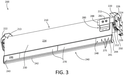
An automatic window shade powers its motor through solar panels at the bottom that touch an upper charging port when opened. Drawing from patent filing US 2026/0366370 A1.
An automatic window shade powers its motor through solar panels at the bottom that touch an upper charging port when opened.All 43 drawings ↓
Publication number
US 2026/0366370 A1(US20260366370A1)
Applicant
Lutron Technology Company LLC
Filed · Published
May 16, 2026 · Nov 19, 2026
Inventors
Ben Matzke
Status when we published
Waiting for an examiner
Document
37 claims
US classification
160/127
Parent application
Claims priority from a provisional application 63807374 (filed May 16, 2025)

What Lutron's solar shade bottom bar does

Imagine you want motorized shades in a room with no outlet near the window, and you don't want an electrician cutting into your walls. Usually that means a battery you have to swap out now and then. Lutron's patent application tries another route: let the sun do the charging.

The solar cells sit on the back of the shade's bottom bar, the weighted strip along the hem, tilted up toward the sky. They fill a small battery inside that bar. Every so often, the shade rolls all the way up to a little dock near the motor, and the bar passes its stored power into the motor's own battery.

The solar-and-battery section is also built to pop off the rest of the bar while the fabric stays attached. The filing says this setup could let you upgrade a manual shade without running new wires.

From the filing · CLAIM 1
… the bottom bar module is configured to be removably detached from the main housing element, the bottom bar module comprising one or more solar cells and one or more first energy storage elements configured to be charged from the one or more solar cells …

Translation: The solar panel and battery pack can be easily unclipped from the bottom of the shade.

How sunlight travels from bottom bar to motor

The claimed system has four main parts: shade fabric hanging from a roller tube, a bottom bar with a detachable solar module, a motor with its own energy storage, and a dock.

  • Solar module: photovoltaic cells (the same kind of cells used in solar panels) sit on a circuit board in a recess on the rear of the bar. The rear face is tilted from vertical, roughly 5 to 75 degrees in the filing, with about 30 as the example, so the cells angle toward the sky.
  • First energy storage: small rechargeable batteries or supercapacitors (parts that store and release charge quickly) in the bar, filled by the cells.
  • Dock: a base near the motor with electrical contacts. When the shade rolls up to its docked position, the bar's contacts touch the dock's, and the stored energy flows into the motor's battery.

The module is removable. A clip at the bottom of the rear housing flexes when you press its release portion, freeing a wedge from a notch, so the whole solar section comes off while the front part stays on the fabric. The solar cell strips can also slide out through a gap that widens when ribs let the housing flex.

The filing also describes sensors, such as occupancy or light sensors, powered by those solar cells, plus spring-loaded contacts and magnets to hold the bar against the dock.

From the filing · THE ABSTRACT
The second housing portion may be configured to be detached from the first housing portion while supporting the one or more solar cell modules and the one or more energy storage elements.

Translation: You can remove part of the bottom rail along with its solar cells and batteries without taking down the whole shade.

Why a solar shade could skip the wiring job

For you, the pitch is a motorized shade that doesn't need an outlet or a trip to the hardware store for batteries. The filing says the motor can be powered entirely from the solar cells, and that the design could upgrade a manual shade without replacing its brackets or running wires. That could matter in rentals, older homes and rooms where the wall is finished and nobody wants to open it up.

The removable module is the practical detail. If the solar section ever fails, it can be unclipped and replaced while the fabric stays hung. Lutron describes shades as one part of a wider home and building control system, with sensors and other devices, so a self-powered shade fits that picture. Keep in mind this is a patent application, not a product.

Lutron is filing its third home tech patent we've tracked since November, adding to earlier applications for a clip-on switch adapter and a keypad with setup buttons.

Source: US 2026/0366370 A1 at the USPTO (PDF). Full patent text and figures are in the official publication.

Get our take in your Top Stories

Liked this breakdown? Add Patentlyze as a preferred source on Google, and our plain-English take shows up more often in your Top Stories the next time Lutron patent news breaks.

There are more where this came from

We read the new patents from Big Tech, carmakers and more and send you the ones worth knowing. Plain English, free, every week.

The drawings · 43 sheets

43 drawing sheets from US 2026/0366370 A1 · click any drawing to enlarge

Smart home devices coordinating shades and lighting across a room, drawing sheet 1 from US 2026/0366370 A1
Sheet 1 Smart home devices coordinating shades and lighting across a room
Front view of the motorized shade mounted on wall brackets, drawing sheet 2 from US 2026/0366370 A1
Sheet 2 Front view of the motorized shade mounted on wall brackets
Solar cells embedded along the window facing hembar, drawing sheet 3 from US 2026/0366370 A1
Sheet 3 Solar cells embedded along the window facing hembar
Roller tube and fabric detached from the wall mounts, drawing sheet 4 from US 2026/0366370 A1
Sheet 4 Roller tube and fabric detached from the wall mounts
Raised hembar approaching the top charging dock, drawing sheet 5 from US 2026/0366370 A1
Sheet 5 Raised hembar approaching the top charging dock
Side profile showing the bottom bar angled toward the charger, drawing sheet 6 from US 2026/0366370 A1
Sheet 6 Side profile showing the bottom bar angled toward the charger
Tubular motor drive unit that fits inside the roller, drawing sheet 7 from US 2026/0366370 A1
Sheet 7 Tubular motor drive unit that fits inside the roller
Charging connector attached to the motor drive unit head, drawing sheet 8 from US 2026/0366370 A1
Sheet 8 Charging connector attached to the motor drive unit head
Show the other 35 sheets
Motor unit views showing electrical contacts for charging, drawing sheet 9 from US 2026/0366370 A1
Sheet 9 Motor unit views showing electrical contacts for charging
Solar cells and exposed contact pins on the bottom bar, drawing sheet 10 from US 2026/0366370 A1
Sheet 10 Solar cells and exposed contact pins on the bottom bar
Roller shade docking into the upper frame to recharge, drawing sheet 11 from US 2026/0366370 A1
Sheet 11 Roller shade docking into the upper frame to recharge
Alternative bottom bar layout with charging pads, drawing sheet 12 from US 2026/0366370 A1
Sheet 12 Alternative bottom bar layout with charging pads
Front and rear exterior of a two-piece bottom bar, drawing sheet 13 from US 2026/0366370 A1
Sheet 13 Front and rear exterior of a two-piece bottom bar
Layers inside the bottom bar facing the room, drawing sheet 14 from US 2026/0366370 A1
Sheet 14 Layers inside the bottom bar facing the room
Window-facing view of the separated bar components, drawing sheet 15 from US 2026/0366370 A1
Sheet 15 Window-facing view of the separated bar components
Detail of the end cap, batteries, and charging board, drawing sheet 16 from US 2026/0366370 A1
Sheet 16 Detail of the end cap, batteries, and charging board
Connecting the solar panel and end cap to the bar, drawing sheet 17 from US 2026/0366370 A1
Sheet 17 Connecting the solar panel and end cap to the bar
Internal layout of the solar charging hembar, drawing sheet 18 from US 2026/0366370 A1
Sheet 18 Internal layout of the solar charging hembar
Front and rear views of an assembled solar hembar, drawing sheet 19 from US 2026/0366370 A1
Sheet 19 Front and rear views of an assembled solar hembar
Exploded front view showing the battery and circuit board, drawing sheet 20 from US 2026/0366370 A1
Sheet 20 Exploded front view showing the battery and circuit board
Exploded rear view showing the row of solar cells, drawing sheet 21 from US 2026/0366370 A1
Sheet 21 Exploded rear view showing the row of solar cells
Detailed front view of the battery and wiring channels, drawing sheet 22 from US 2026/0366370 A1
Sheet 22 Detailed front view of the battery and wiring channels
Rear angle showing how the control board fits inside, drawing sheet 23 from US 2026/0366370 A1
Sheet 23 Rear angle showing how the control board fits inside
Mounting the opposite end cap onto the bar assembly, drawing sheet 24 from US 2026/0366370 A1
Sheet 24 Mounting the opposite end cap onto the bar assembly
Angled solar panel mounted along the bottom bar, drawing sheet 25 from US 2026/0366370 A1
Sheet 25 Angled solar panel mounted along the bottom bar
Front and rear views of a solar-powered bottom bar, drawing sheet 26 from US 2026/0366370 A1
Sheet 26 Front and rear views of a solar-powered bottom bar
Front view of parts inside the solar bottom bar, drawing sheet 27 from US 2026/0366370 A1
Sheet 27 Front view of parts inside the solar bottom bar
Rear parts that power the solar bottom bar, drawing sheet 28 from US 2026/0366370 A1
Sheet 28 Rear parts that power the solar bottom bar
Close-up of the control circuit and battery at one end, drawing sheet 29 from US 2026/0366370 A1
Sheet 29 Close-up of the control circuit and battery at one end
Opposite end of the bottom bar showing its mounting channels, drawing sheet 30 from US 2026/0366370 A1
Sheet 30 Opposite end of the bottom bar showing its mounting channels
Wiring and circuit board setup inside the bottom bar, drawing sheet 31 from US 2026/0366370 A1
Sheet 31 Wiring and circuit board setup inside the bottom bar
Solar panel segments fitting into the rear housing slots, drawing sheet 32 from US 2026/0366370 A1
Sheet 32 Solar panel segments fitting into the rear housing slots
Angling solar cells inside the bottom bar to catch sunlight, drawing sheet 33 from US 2026/0366370 A1
Sheet 33 Angling solar cells inside the bottom bar to catch sunlight
Circuits that route solar energy into the motor's battery, drawing sheet 34 from US 2026/0366370 A1
Sheet 34 Circuits that route solar energy into the motor's battery
Moving the window shade when a user sends a command, drawing sheet 35 from US 2026/0366370 A1
Sheet 35 Moving the window shade when a user sends a command
Deciding to dock the shade bar when room occupants leave, drawing sheet 36 from US 2026/0366370 A1
Sheet 36 Deciding to dock the shade bar when room occupants leave
Checking the sun's position before raising shades to charge, drawing sheet 37 from US 2026/0366370 A1
Sheet 37 Checking the sun's position before raising shades to charge
Sensing overcast skies to recharge while natural light is low, drawing sheet 38 from US 2026/0366370 A1
Sheet 38 Sensing overcast skies to recharge while natural light is low
Respecting privacy modes and darkness before moving the shade, drawing sheet 39 from US 2026/0366370 A1
Sheet 39 Respecting privacy modes and darkness before moving the shade
Raising the shade into its charging dock at the top, drawing sheet 40 from US 2026/0366370 A1
Sheet 40 Raising the shade into its charging dock at the top
Adjusting how often the shade docks based on battery levels, drawing sheet 41 from US 2026/0366370 A1
Sheet 41 Adjusting how often the shade docks based on battery levels
Changing the shade docking schedule to match daylight trends, drawing sheet 42 from US 2026/0366370 A1
Sheet 42 Changing the shade docking schedule to match daylight trends
Moving the shade until solar cells catch enough light, drawing sheet 43 from US 2026/0366370 A1
Sheet 43 Moving the shade until solar cells catch enough light
Patent filing page

More from Lutron

All 3 Lutron patents →
Reader comments

No comments yet

Start the discussion

Real name or a handle, either is fine. Comments are read by a person before they appear, so allow a little time. Keep it about the filing.