Get the newsletter
Sony · Cell phone · Filed May 21, 2025 · USPTO published Nov 12, 2026 · This week's release

Sony Patents a Tiny Laser Whose Light Waves All Line Up the Same Way

Tiny lasers in phones and cars can send out light that wiggles in a different direction from one chip to the next. Sony's patent application fixes that with a mirror-like edge placed beside the glowing spot.
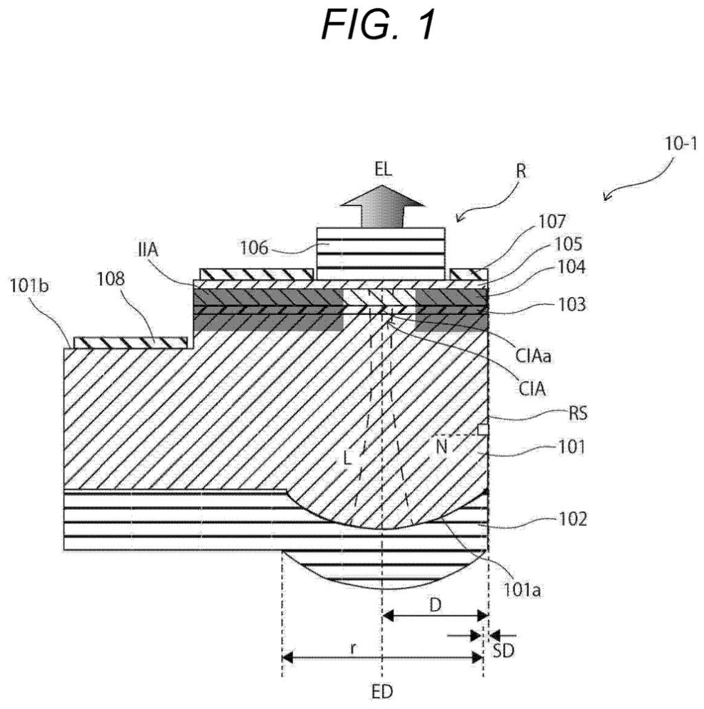
Cutaway view of a tiny light beam generator bouncing rays through a curved bottom to shoot an orderly beam upward. Drawing from patent filing US 2026/0361053 A1.
Cutaway view of a tiny light beam generator bouncing rays through a curved bottom to shoot an orderly beam upward.All 55 drawings ↓
Publication number
US 2026/0361053 A1(US20260361053A1)
Applicant
Sony Group Corporation
Filed · Published
May 21, 2025 · Nov 12, 2026
Inventors
Tomohiro MAKINO, Tatsushi HAMAGUCHI
Status when we published
Waiting for an examiner
Document
20 claims
US classification
372/45.01
Parent application
National Stage Entry of PCT/JP2023/040712 (filed Nov 13, 2023)(PCTJP2023040712)

What Sony's one-direction laser actually does

Imagine a hundred people each shaking a jump rope. Some shake theirs up and down, some side to side, and a few switch halfway through. Light from many tiny lasers behaves a bit like that: the direction its waves wiggle, called polarization, can differ from one chip to the next and can even flip while the laser runs.

Plenty of devices work better when every beam wiggles the same way, and older fixes had costs. One etched a fine pattern right where the light exits, which can waste power and gets harder to build for blue light. Another squeezed the glowing layer, but the direction could still jump between two settings.

Sony's idea is to put a mirror-like edge beside the glowing spot, never on top of it. The edge bounces a little light sideways, and the beam leaving the top settles into the direction that runs parallel to the edge. In the filing's examples, 90% or more of the light lines up.

From the filing · CLAIM 1
… a reflection portion having a reflection surface, wherein the reflection portion is located outside a current injection region of the active layer in plan view, and a normal line of the reflection surface is not parallel to an emission direction.

Translation: A tiny mirrored surface is placed just outside the laser's power zone to steer the light waves.

How a cut edge steers the laser's light

The device is a vertical cavity surface emitting laser, or VCSEL: a sandwich with a mirror on the bottom, a mirror on top, and a light-producing layer (the active layer) in between. Light bounces between the mirrors, builds up, and leaves the top as a beam.

The claim adds a reflection portion: a surface that sits outside the area where electric current flows into the active layer (the current injection region, where the light is actually made). Its angle is set so that a line standing straight out from the surface does not point along the beam. Think of a mirrored wall at the side of a stage.

That surface keeps some light bouncing sideways inside the chip, in a thin layer that guides light (a slab waveguide). The sideways light couples with the up-and-down light, and the beam settles into the wiggle direction parallel to the surface. The filing reports a polarization ratio of 90% or more, for example 95%.

The filing also describes these variations:

  • The edge can be a cleaved surface: a diamond cutter scratches a line and the chip is snapped along it.
  • It can also be the wall of an etched trench or notch.
  • The edge sits within 1,000 micrometers of the emitter, and the filing prefers 20 or less.
  • In arrays, nine emitters can share one edge to line up together, or different edges can point groups of emitters different ways.
From the filing · THE ABSTRACT
… stably controlling a polarization direction while suppressing a decrease in efficiency.

Translation: It keeps all the light waves lined up together without wasting battery power.

Why phone and car sensors could care

Lasers this small sit inside distance sensors, and the filing names smartphones, smart watches, drones, robots and cars as places such sensors could go. It also lists projectors, head-mounted displays and laser printers. The filing notes that, depending on the application, controlling the light's direction is desirable.

For you, the payoff would be indirect: sensors that behave more consistently from unit to unit, without the power loss of older fixes. This is a patent application, so nothing says Sony will build it. The filing names no product and describes a component rather than a gadget.

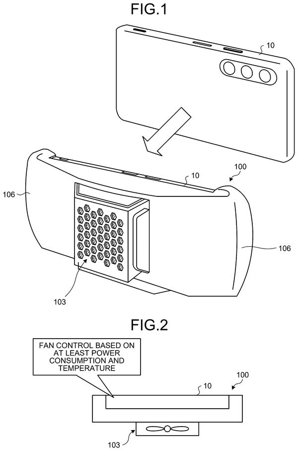
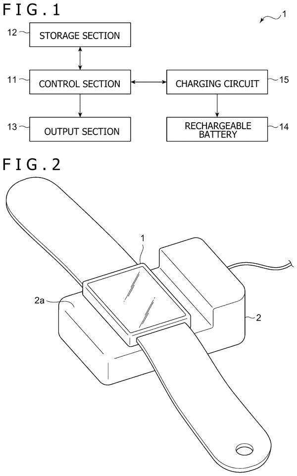
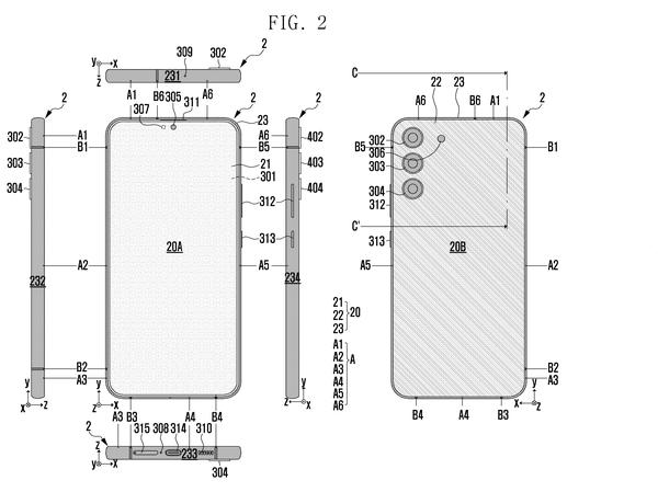
Sony's 13th filing we've tracked in our cell phone coverage since May follows a clip-on fan patent and a charging alert system as Sony keeps applying around phone hardware and power.

Source: US 2026/0361053 A1 at the USPTO (PDF). Full patent text and figures are in the official publication.

Get our take in your Top Stories

Liked this breakdown? Add Patentlyze as a preferred source on Google, and our plain-English take shows up more often in your Top Stories the next time Sony patent news breaks.

There are more where this came from

We read every patent application Big Tech publishes and send you the ones worth knowing. Plain English, free, every week.

The drawings · 55 sheets

55 drawing sheets from US 2026/0361053 A1 · click any drawing to enlarge

Internal layers and curved base that align the laser beam, drawing sheet 1 from US 2026/0361053 A1
Sheet 1 Internal layers and curved base that align the laser beam
Top view of the laser showing the polarization direction, drawing sheet 2 from US 2026/0361053 A1
Sheet 2 Top view of the laser showing the polarization direction
Steps for building the tiny surface laser, drawing sheet 3 from US 2026/0361053 A1
Sheet 3 Steps for building the tiny surface laser
Growing crystal layers and carving a contact step, drawing sheet 4 from US 2026/0361053 A1
Sheet 4 Growing crystal layers and carving a contact step
Adding ion barriers and a transparent conductive film, drawing sheet 5 from US 2026/0361053 A1
Sheet 5 Adding ion barriers and a transparent conductive film
Attaching electrical contacts and the top mirror stack, drawing sheet 6 from US 2026/0361053 A1
Sheet 6 Attaching electrical contacts and the top mirror stack
Shaping the bottom curved lens and adding reflective coating, drawing sheet 7 from US 2026/0361053 A1
Sheet 7 Shaping the bottom curved lens and adding reflective coating
Cleaving one side to produce a flat reflective wall, drawing sheet 8 from US 2026/0361053 A1
Sheet 8 Cleaving one side to produce a flat reflective wall
Show the other 47 sheets
Side view showing curved bottom mirror set back from edge, drawing sheet 9 from US 2026/0361053 A1
Sheet 9 Side view showing curved bottom mirror set back from edge
Top view showing how edge angles determine wave orientation, drawing sheet 10 from US 2026/0361053 A1
Sheet 10 Top view showing how edge angles determine wave orientation
Narrow chip design bounded by two parallel cleaved walls, drawing sheet 11 from US 2026/0361053 A1
Sheet 11 Narrow chip design bounded by two parallel cleaved walls
Overhead view of the narrow design between twin wall cuts, drawing sheet 12 from US 2026/0361053 A1
Sheet 12 Overhead view of the narrow design between twin wall cuts
Reflective coating added to the side wall to steer waves, drawing sheet 13 from US 2026/0361053 A1
Sheet 13 Reflective coating added to the side wall to steer waves
Looking down at the side mirror layer lining one edge, drawing sheet 14 from US 2026/0361053 A1
Sheet 14 Looking down at the side mirror layer lining one edge
Protective outer coating applied along the reflective edge, drawing sheet 15 from US 2026/0361053 A1
Sheet 15 Protective outer coating applied along the reflective edge
Bird's eye layout featuring an edge sealed by shielding, drawing sheet 16 from US 2026/0361053 A1
Sheet 16 Bird's eye layout featuring an edge sealed by shielding
Two cross sections showing patterned layers atop the laser, drawing sheet 17 from US 2026/0361053 A1
Sheet 17 Two cross sections showing patterned layers atop the laser
Looking down at bow tie cutouts that align laser waves, drawing sheet 18 from US 2026/0361053 A1
Sheet 18 Looking down at bow tie cutouts that align laser waves
Vertical cross sections of a design with a round mirror, drawing sheet 19 from US 2026/0361053 A1
Sheet 19 Vertical cross sections of a design with a round mirror
Overhead view showing a circular mirror near a flat edge, drawing sheet 20 from US 2026/0361053 A1
Sheet 20 Overhead view showing a circular mirror near a flat edge
Adding a deep trench to bounce and align light inside, drawing sheet 21 from US 2026/0361053 A1
Sheet 21 Adding a deep trench to bounce and align light inside
Grooves carved around the laser to shape light beams, drawing sheet 22 from US 2026/0361053 A1
Sheet 22 Grooves carved around the laser to shape light beams
Steps for manufacturing the trench-isolated laser diode, drawing sheet 23 from US 2026/0361053 A1
Sheet 23 Steps for manufacturing the trench-isolated laser diode
Growing crystal layers and treating areas to steer current, drawing sheet 24 from US 2026/0361053 A1
Sheet 24 Growing crystal layers and treating areas to steer current
Adding a clear top film and exposing the base contact, drawing sheet 25 from US 2026/0361053 A1
Sheet 25 Adding a clear top film and exposing the base contact
Carving a deep side trench and attaching electrical contacts, drawing sheet 26 from US 2026/0361053 A1
Sheet 26 Carving a deep side trench and attaching electrical contacts
Stacking the upper mirror and shaping the bottom curved lens, drawing sheet 27 from US 2026/0361053 A1
Sheet 27 Stacking the upper mirror and shaping the bottom curved lens
Coating the bottom lens with a reflective mirror layer, drawing sheet 28 from US 2026/0361053 A1
Sheet 28 Coating the bottom lens with a reflective mirror layer
An alternative laser design using an open side edge, drawing sheet 29 from US 2026/0361053 A1
Sheet 29 An alternative laser design using an open side edge
How the beam aligns with the cut edge from above, drawing sheet 30 from US 2026/0361053 A1
Sheet 30 How the beam aligns with the cut edge from above
Etching an open side step before wiring the contacts, drawing sheet 31 from US 2026/0361053 A1
Sheet 31 Etching an open side step before wiring the contacts
Depositing the top mirror stack and curving the bottom base, drawing sheet 32 from US 2026/0361053 A1
Sheet 32 Depositing the top mirror stack and curving the bottom base
Cleaving one side to produce a flat reflective wall, drawing sheet 33 from US 2026/0361053 A1
Sheet 33 Cleaving one side to produce a flat reflective wall
Adding a multilayer mirror along the cleaved edge, drawing sheet 34 from US 2026/0361053 A1
Sheet 34 Adding a multilayer mirror along the cleaved edge
Top view of the laser with a side mirror stack, drawing sheet 35 from US 2026/0361053 A1
Sheet 35 Top view of the laser with a side mirror stack
Replacing the side mirror stack with a metal coating, drawing sheet 36 from US 2026/0361053 A1
Sheet 36 Replacing the side mirror stack with a metal coating
Overhead layout of the laser with a metal side mirror, drawing sheet 37 from US 2026/0361053 A1
Sheet 37 Overhead layout of the laser with a metal side mirror
Aligning an entire grid of lasers using a single edge, drawing sheet 38 from US 2026/0361053 A1
Sheet 38 Aligning an entire grid of lasers using a single edge
Two parallel cleaved edges bounding a laser grid, drawing sheet 39 from US 2026/0361053 A1
Sheet 39 Two parallel cleaved edges bounding a laser grid
Perpendicular edges orienting lasers in two directions, drawing sheet 40 from US 2026/0361053 A1
Sheet 40 Perpendicular edges orienting lasers in two directions
Multiple laser emitters arranged in a hexagonal layout, drawing sheet 41 from US 2026/0361053 A1
Sheet 41 Multiple laser emitters arranged in a hexagonal layout
An undercut sidewall angled to steer stray reflections away, drawing sheet 42 from US 2026/0361053 A1
Sheet 42 An undercut sidewall angled to steer stray reflections away
Shifting the angled sidewall further outward from the laser, drawing sheet 43 from US 2026/0361053 A1
Sheet 43 Shifting the angled sidewall further outward from the laser
A stepped sidewall setting the lower reflective edge back, drawing sheet 44 from US 2026/0361053 A1
Sheet 44 A stepped sidewall setting the lower reflective edge back
Combining a vertical base wall with a sloped upper bevel, drawing sheet 45 from US 2026/0361053 A1
Sheet 45 Combining a vertical base wall with a sloped upper bevel
A peaked outer edge angled inward at top and bottom, drawing sheet 46 from US 2026/0361053 A1
Sheet 46 A peaked outer edge angled inward at top and bottom
An indented V shaped notch cut into the chip sidewall, drawing sheet 47 from US 2026/0361053 A1
Sheet 47 An indented V shaped notch cut into the chip sidewall
Curved outer edges scatter stray laser waves in all directions, drawing sheet 48 from US 2026/0361053 A1
Sheet 48 Curved outer edges scatter stray laser waves in all directions
A curved reflective side wall helps align the laser beam, drawing sheet 49 from US 2026/0361053 A1
Sheet 49 A curved reflective side wall helps align the laser beam
Shifting the reflective wall closer keeps light waves aligned, drawing sheet 50 from US 2026/0361053 A1
Sheet 50 Shifting the reflective wall closer keeps light waves aligned
Angled reflective edges bounce light back into the emitter, drawing sheet 51 from US 2026/0361053 A1
Sheet 51 Angled reflective edges bounce light back into the emitter
An embedded trench reflects light inside the chip, drawing sheet 52 from US 2026/0361053 A1
Sheet 52 An embedded trench reflects light inside the chip
Using the laser in a depth sensor to gauge distances, drawing sheet 53 from US 2026/0361053 A1
Sheet 53 Using the laser in a depth sensor to gauge distances
Connecting the laser sensor to a car control computer, drawing sheet 54 from US 2026/0361053 A1
Sheet 54 Connecting the laser sensor to a car control computer
Where laser distance sensors sit around a self driving car, drawing sheet 55 from US 2026/0361053 A1
Sheet 55 Where laser distance sensors sit around a self driving car
Patent filing page

Reader comments

No comments yet

Start the discussion

Real name or a handle, either is fine. Comments are read by a person before they appear, so allow a little time. Keep it about the filing.