
Disney
Disney · Sensor · Filed Feb 14, 2025 · USPTO published Aug 20, 2026 · Aug 20 release
Disney Patents a System That Tracks Ride Vehicles Between Sensor Points
Disney has filed a patent for a system that knows where a ride vehicle is even when no sensor is directly watching it, using physics calculations to fill in the blanks between checkpoints.
- Publication number
- US 2026/0245466 A1(US20260245466A1)
- Applicant
- DISNEY ENTERPRISES, INC.
- Filed · Published
- Feb 14, 2025 · Aug 20, 2026
- Inventors
- Sylvester Venansius Kwo, Stephen Burns, Sarah Julia Myerson, Brian Foster Walters, Michael Tschanz, Alicia Hofer, Rolando Bulnes, Brandyn Dean Burbank
- Status when we published
- Company responded; back with the examiner
- Document
- 20 claims
- US classification
- 340/425.5
- Examiner
- CASILLASHERNANDEZ, OMAR (Art Unit 2689)
How Disney fills the gaps in ride vehicle tracking
You're riding a rollercoaster or a dark ride, and behind the scenes, operators need to know exactly where every car is on the track at every moment. Placing a physical sensor at every foot of track would be wildly expensive and impractical, so there have always been blind spots.
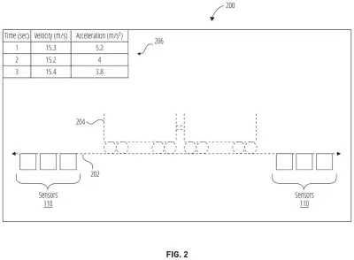
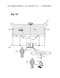
Disney's patent describes a way to eliminate those blind spots without adding more hardware. A set of sensors is spread out along the track, each one working independently. When a vehicle passes a sensor, that sensor records data about the car's speed and position. The system then uses that real data, combined with everything already known about the track's shape and layout, to mathematically calculate where the vehicle must be in between those sensor points.
The result is a continuously updated picture of the whole track, displayed on a screen for operators. Instead of seeing a car "arrive" at checkpoint A and then "arrive" at checkpoint B with nothing in between, staff see a smooth, real-time model of every vehicle's journey across the entire route.
… determine infilling kinematic data representative of the path-based vehicle at one or more positions between the plurality of sensors based on the vehicle data and known path characteristics …
Translation: Calculate where the ride vehicle is between physical sensors using math and the layout of the track
How the infilling calculation bridges sensor gaps
The system has three main parts working together.
- Distributed sensors: Physical sensors are placed at intervals along a fixed, known track. Crucially, each sensor operates on its own, meaning the system does not rely on one central sensor array. If one sensor fails, the others keep reporting independently.
- Infilling kinematic data: "Kinematics" is the physics of motion, covering position, speed, and direction. When the sensors report where a vehicle was and how fast it was going at those checkpoints, the processing unit applies the known geometry of the track (its curves, slopes, and length) to calculate what the vehicle's motion must have been in the gaps between sensors. This calculated data is called "infilling" data because it fills in what was not directly measured.
- System model and visualization: All of this, the real sensor readings and the calculated in-between data, feeds into a unified model of the entire track system. That model is rendered as a visual display, giving operators a continuous, high-resolution picture of vehicle positions across the whole route rather than a series of disconnected snapshots.
The claim is written broadly: it covers any "path-based vehicle" on a "known path," which means the underlying method could apply to any guided-vehicle system where the track layout is fixed and pre-mapped.
… generate a visualization of the infilling kinematic data, the path-based vehicle data, and the known path information …
Translation: Create a visual map showing the predicted and actual positions of the ride vehicle
What this means for theme park ride safety systems
For theme park operations, knowing where every vehicle is at all times is a safety and efficiency requirement. Traditional sensor setups give operators a series of checkpoints, not a continuous picture. This system effectively turns a sparse sensor network into something that behaves like a much denser one, without the cost of physically installing hardware at every point.
The claim language is broad. It covers any "path system" with a "known path," so the core method could extend well beyond theme park rides to any guided-transit application where the route is fixed. Disney-related ride patents are part of the wider flow of newest Big Tech patents covering automated tracking and position-modeling technology, a field that sits at the intersection of entertainment infrastructure and industrial sensing.
Disney's 31st filing we've tracked in our Disney coverage since June follows work on projecting images on moving surfaces and catching failing park equipment early.
Source: US 2026/0245466 A1 at the USPTO (PDF). Full patent text and figures are in the official publication.
Get our take in your Top Stories
Liked this breakdown? Add Patentlyze as a preferred source on Google, and our plain-English take shows up more often in your Top Stories the next time Disney patent news breaks.
Add Patentlyze on Google
One click.
There are more where this came from
We read the new patents from Big Tech, carmakers and more and send you the ones worth knowing. Plain English, free, every week.
The drawings · 4 sheets
4 drawing sheets from US 2026/0245466 A1 · click any drawing to enlarge


More from Disney
All 64 Disney patents →
More in Hardware
All 2,375 Hardware patents →
Sony
Sony Files Patent for a Compact Signal-Tracking System That Pinpoints Where a Transmission Comes From
Sony
Sony Patents an Electromagnetic Scanner That Decides How Hard to Look
Samsung
Samsung Patents an Air Conditioner That Adjusts Based on Where You Move
Samsung