
Samsung
Samsung · Robotics · Filed Mar 4, 2026 · USPTO published Nov 19, 2026 · This week's release
Samsung Patents a Robot Vacuum Mop That Springs Back After Hitting Furniture
A mop pad that sticks out past a robot vacuum's body is exposed to every chair leg in the house. Samsung's new patent puts a spring in the mechanism so the pad gives way on impact and returns to its place afterward.
- Publication number
- US 2026/0363516 A1(US20260363516A1)
- Applicant
- SAMSUNG ELECTRONICS CO., LTD.
- Filed · Published
- Mar 4, 2026 · Nov 19, 2026
- Inventors
- Byoungin LEE, Ahreum HAN
- Status when we published
- Waiting for an examiner
- Document
- 16 claims
- US classification
- 15/98
- Parent application
- Continuation of PCT/KR2026/002725 (filed Feb 13, 2026)(PCTKR2026002725)
What Samsung's spring-loaded mop pad actually does
Your robot vacuum is working along the wall, with its mop pad swung out past the edge of its body to reach more floor. Then it clips a chair leg. A pad sticking out like that takes every bump first.
Samsung's patent describes a mop pad that gives way when it is hit. The pad is linked to its motor through a small set of gears and a spring. When something pushes the pad inward, the spring squeezes. Once the obstacle is gone, the spring pushes the pad back out to its extended position. If it doesn't quite make it, the motor steps in to finish the job.
The filing also describes a lock for the opposite situation. While the pad is tucked in and spinning, friction with the floor can tug it outward, so a thicker section on one gear holds it in place.
… a cleaning pad movable to a first position and a second position, the cleaning pad spaced farther from a center of the housing in the second position than in the first position …
Translation: The mop pad can extend outward to reach edges or retract closer to the body.
How the gears and spring move the mop pad
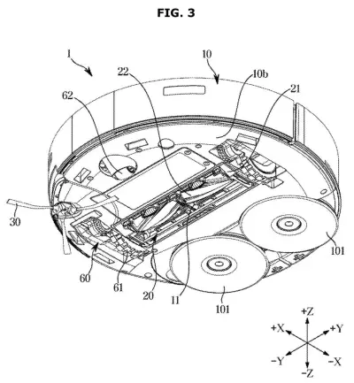
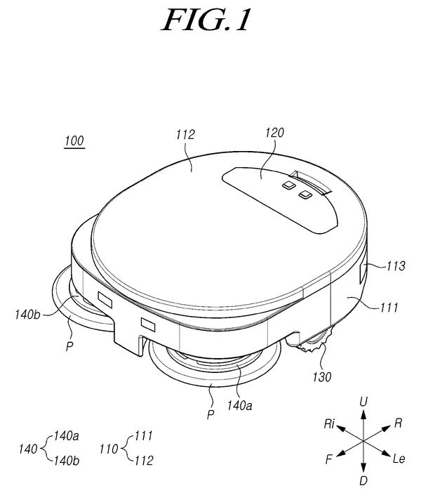
The claims cover a cleaner (the filing uses a robot vacuum as its main example, and says stick and canister vacuums could use the idea too) with a body and a cleaning pad that can sit in two spots. The first position is closer to the center of the body, and the second position is farther out, which widens the area the pad can reach. A "pad moving device" shuttles the pad between them.
That device has five main parts:
- A motor (the "moving drive source") that supplies the power.
- A lever gear that the motor turns.
- A guide gear that meshes with the lever gear and turns the opposite way.
- A guide lever, an arm connected to the mount that holds the pad.
- A spring (the "elastic member") between the guide gear and the guide lever. The filing mentions compression springs and twisting springs.
The key claim is what happens on a collision. If an obstacle shoves the pad out of its extended position, the lever compresses the spring, and the pad slides to an in-between third position. When the push stops, the spring forces the pad back out. The description says a small bump is absorbed because the motor holds the gears still, while a harder hit is big enough to turn them.
A position sensor can tell when the pad has left its extended spot. A controller then runs the motor until the pad is back and shuts it off once it arrives. A cover with a stopper also limits how far the lever gear can turn.
… an elastic member elastically deformable and configured to rotate the guide lever relative the guide gear and such that, with an obstacle moving the cleaning pad from the second position, the elastic member forces the cleaning pad toward the second position …
Translation: A spring mechanism snaps the pad back into place after bumping into furniture.
Why a mop that survives furniture hits matters
If you own a robot vacuum with a mop, the practical gains are reach and reliability. A pad that swings out past the body covers more floor. A spring that lets the pad give way against a chair leg means it returns to position instead of staying knocked out of line. Samsung's stated aims are better pad movement and stable cleaning.
For Samsung, this is a refinement to the moving parts of a mop-equipped robot vacuum. The filing names no product, and nothing in it says whether or when the idea would ship. It is a mechanical fix, and the company explains it with gears, springs and one sensor.
This is the 59th Samsung filing we've tracked since May on our home robot filings, building on a moving mop dock nozzle and lifting-wheel correction.
Source: US 2026/0363516 A1 at the USPTO (PDF). Full patent text and figures are in the official publication.
Get our take in your Top Stories
Liked this breakdown? Add Patentlyze as a preferred source on Google, and our plain-English take shows up more often in your Top Stories the next time Samsung patent news breaks.
Add Patentlyze on Google
One click.
There are more where this came from
We read every patent application Big Tech publishes and send you the ones worth knowing. Plain English, free, every week.
The drawings · 25 sheets
25 drawing sheets from US 2026/0363516 A1 · click any drawing to enlarge


Show the other 17 sheets


More from Samsung
All 1,662 Samsung patents →
More in Hardware
All 2,355 Hardware patents →
Samsung
Samsung Patents a Robot Vacuum That Reads Floor Surfaces with Sound Waves
Samsung
Samsung Patents a Shaped Wheel That Guides Robot Vacuums Straight onto Their Charging Base
Samsung
Samsung Patents a Self-Descaling Docking Station for Robot Mops
Samsung
No comments yet