
Samsung
Samsung · Cell phone · Filed Jul 14, 2026 · USPTO published Nov 19, 2026 · This week's release
Samsung Patents a Phone Zoom Camera That Steadies Shaky Hands in Less Space
When you zoom way in, every tiny tremble in your hand gets magnified. Samsung's patent application changes which directions the camera's internal mirror tilts to cancel that shake, and says the change saves room inside the camera.
- Publication number
- US 2026/0370940 A1(US20260370940A1)
- Applicant
- Samsung Electronics Co., Ltd.
- Filed · Published
- Jul 14, 2026 · Nov 19, 2026
- Inventors
- Jiyeon JO, Hyungjin RHO, Jeongkil SHIN, Jaekyu SHIM, Jeongyeol LEE
- Status when we published
- Waiting for an examiner
- Document
- 20 claims
- US classification
- 348/208.99
- Parent application
- Continuation of PCT/KR2025/000929 (filed Jan 16, 2025)(PCTKR2025000929)
What Samsung's folded zoom camera actually does
Every time you zoom in on a far-off stage or a bird in a tree, your hand wobbles, and the zoomed view wobbles far more than the wide one. Phones fight this with optical image stabilization, which physically moves a part inside the camera to cancel your shake.
Samsung's patent application covers a zoom camera that bends light sideways with a small mirror or prism, then tilts that mirror to cancel the wobble. The twist is in how it tilts. Instead of spinning the mirror around the axis that points straight at your subject, it tilts it in two other directions, like a head nodding and a head turning. The filing says this needs less empty space around the moving part and twists the picture less during correction.
On paper, that means a stabilizer that fits in a slimmer camera module and keeps zoomed shots from rotating as the mirror moves.
… one or more first optical image stabilizer (OIS) balls disposed between the first guide groove and the second guide groove; a second OIS ball disposed between the third guide groove and the fourth guide groove …
Translation: Tiny metal balls help the camera parts glide smoothly to counteract hand shakes.
How the mirror platform tilts on tiny balls
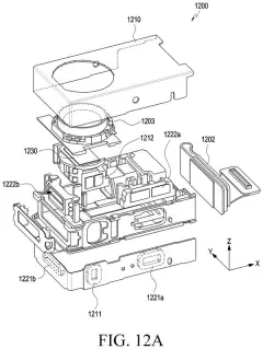
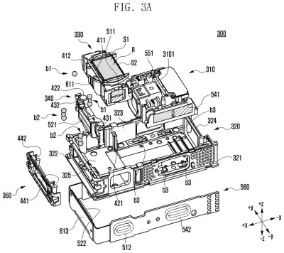
Inside the module, light enters through one face of a reflective member (a small prism or mirror), bounces off an angled surface, and exits at a right angle toward a lens and the image sensor. Folding the light path like this is how a high-zoom camera fits inside a thin phone. The mirror sits on a carrier, a small platform that can tilt.
The stabilizer is a stack of three parts:
- A base fixed to the camera housing.
- A middle guide that sits on the base and rotates on tiny steel balls rolling in curved grooves.
- The carrier, which sits on the middle guide and rotates on its own set of balls.
Each rotation has its own magnet and coil. Current through a coil creates a Lorentz force (the push a magnet exerts on a wire carrying current), which tilts the part. One pair tilts the carrier around the axis of the exiting light, and the other tilts the middle guide, and the carrier with it, around a second axis at a right angle to the first.
Smaller details are described too. On the main groove track, three balls guide the motion, with one ball on the side track. V-shaped grooves hold balls in line, while looser U-shaped grooves absorb small manufacturing differences. Extra attraction magnets keep the parts pressed against the balls and pull the carrier back to center when power is off. A second claim describes tilting around an axis slanted at about 45 degrees.
… a reflective member including an incident surface and an exit surface perpendicular to the incident surface …
Translation: An angled mirror bends the path of light so the telephoto lens fits inside a slim phone.
What this means for phone zoom cameras
Zoom is where hand shake hurts most, so stabilization in a zoom camera decides whether your photo of a concert or a distant animal comes out sharp. Squeezing that stabilizer into less space helps phone makers keep the camera bump from growing as zoom lenses get more ambitious.
The filing's pitch is a trade of smaller gaps and less picture twisting for a different mix of tilt directions, plus a few mechanical tricks such as magnets that stack in the thickness direction. The patent gives no measurements, so how much thinner or steadier it gets is unknown. It also does not name a product.
That makes this Samsung's 172nd filing we've tracked since May in our camera sensor work, following applications like one fixing autofocus confusion and one cutting dark-photo stripes.
Source: US 2026/0370940 A1 at the USPTO (PDF). Full patent text and figures are in the official publication.
Get our take in your Top Stories
Liked this breakdown? Add Patentlyze as a preferred source on Google, and our plain-English take shows up more often in your Top Stories the next time Samsung patent news breaks.
Add Patentlyze on Google
One click.
There are more where this came from
We read every patent application Big Tech publishes and send you the ones worth knowing. Plain English, free, every week.
The drawings · 23 sheets
23 drawing sheets from US 2026/0370940 A1 · click any drawing to enlarge


Show the other 15 sheets


More from Samsung
All 1,662 Samsung patents →

More in Cell phone
All 494 Cell phone patents →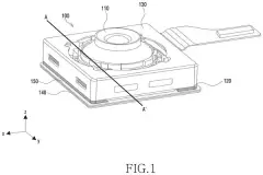
Samsung
Samsung Files Patent for a Slimmer Phone Camera With Focus Parts Tucked Into Its Base
Samsung
Samsung Files Patent for a Camera Sensor That Keeps Autofocus Working in Bright Light
Samsung
Samsung Patents a Way to Use Your Selfie Camera to Fix Rear Photo Colors
Samsung
No comments yet