
Sony · Filed Jul 14, 2026 · Published Nov 5, 2026

Sony Files Patent for a Camera Sensor That Handles Both Dim Rooms and Bright Sun

A camera sensor that captures every pixel at the same instant has a noise problem, and Sony's fix is to let each pixel read light two ways, one for dim scenes and one for blinding ones, with a different-sized storage spot for each.
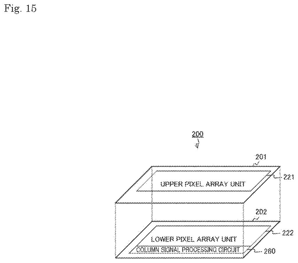
Two stacked silicon layers inside a camera split capturing photos from turning them into digital files. Drawing from patent filing US 2026/0352974 A1.
Two stacked silicon layers inside a camera split capturing photos from turning them into digital files.
See all 79 drawings from this filing ↓
Publication number US 2026/0352974 A1 US20260352974A1
Applicant SONY SEMICONDUCTOR SOLUTIONS CORPORATION
Filing date Jul 14, 2026
Publication date Nov 5, 2026
Inventors Ryoto YOSHITA, Takashi MACHIDA, Luonghung ASAKURA, Yoshiaki INADA, Yoshimichi KUMAGAI, Toru SHIRAKATA
US classification 348/300
Status when we published Waiting for an examiner (Jul 30, 2026)
Parent application is a Continuation of 18699397 (filed 2024-04-08)
Document 22 claims

What Sony's two-gear camera pixel actually does

A phone camera points at a dim restaurant table, then swings toward a window full of afternoon sun. Those two scenes ask very different things of the sensor, and a sensor tuned for one tends to struggle with the other.

Sony's patent application is about a type of sensor that exposes every pixel at the same moment. These sensors hold each pixel's reading in a tiny electrical storage cell until it can be sent out, and that holding step adds noise, which shows up as grain. The earlier design Sony points to couldn't change how strongly it turns light into a signal, so dim scenes came out too weak and bright ones could clip.

Sony's version lets each pixel read light at two strengths, one for dim scenes and one for bright ones, and gives every reading its own storage cell. The cell for the sensitive, dim-light reading is made larger, since that is where noise does the most damage. In practice, your photos could hold on to both shadows and highlights.

From the filing · CLAIM 1
a high capacitive element whose capacitance value is higher than a predetermined value, and a low capacitive element whose capacitance value is lower than the predetermined value …

Translation: The sensor uses different circuit parts to handle bright light and dark shadows separately.

How Sony sizes the storage cells for each gear

The core is a pixel that can turn captured light into a voltage at more than one conversion efficiency (how much voltage you get for each bit of light collected). High efficiency suits dim scenes. Low efficiency suits bright ones, where a pixel would otherwise fill up and clip.

After the exposure ends, the pixel sends out its readings one after another: a reset level and a signal level at high efficiency, then the same pair at low efficiency. Each reading is parked in its own capacitive element (a tiny electrical storage cell). All the cells share one connection on the input side, and a selection circuit (a set of switches) links just one at a time to the readout. The chip then subtracts the reset level from the signal level to cancel out offsets, and can choose the high or low reading for a whole frame or pixel by pixel, depending on brightness.

The claimed twist is that the cells come in different sizes. The high-efficiency reading goes into a bigger cell, because a larger cell cuts kTC noise (random electrical fuzz created when a voltage is sampled), and that fuzz matters most at high efficiency. The filing describes several ways to build the bigger cell:

  • Give it a larger area.
  • Use a denser capacitor material in the same footprint.
  • Wire several identical small cells together so they act as one.

A separate independent claim covers another route: two extra capacitors of different sizes, attached to the pixel's charge-collecting spot through two switches, so the pixel can step through several gain levels.

From the filing · THE ABSTRACT
In a solid-state imaging element that performs exposure in all pixels at the same time, image quality is improved.

Translation: Exposing every pixel simultaneously helps the camera produce much clearer pictures.

What this means for low-light and bright photos

If you shoot in a dim room one minute and bright sun the next, a sensor that adapts for each pixel could keep more detail at both ends without piling on grain. The filing says the sensor would go into a digital camera or a device with a camera, such as a smartphone or personal computer, and it also describes a vehicle application.

For Sony, which designs image sensors through its semiconductor unit, the value is in fixing a known weakness of this sensor type: earlier designs could not change their gain. The filing continues an earlier application first filed in Japan in October 2021. A published application is a request for protection, not a product announcement.

Sony's 97th filing in Display patents we cover since May follows one on shrinking panel circuits and one on flagging image regions.

Editorial take

Every extra storage cell inside a pixel costs room, and pixels are already tiny. Sony's design asks each one to carry four holding spots instead of two, plus the switches to pick between them, and the biggest of those spots has to be even bigger.

The filing is open about that squeeze. It spreads the parts across stacked chips, packs more storage into the same footprint, or wires several small identical cells together so they act as one large one. Each route adds manufacturing complexity, and the description says one variant is partly meant to hold down development costs.

The trade looks sensible anyway. Spending space only where noise hurts most, on the sensitive dim-light reading, is a targeted choice, and the payoff is a camera that no longer has to pick between good shadows and unclipped highlights. The open risk is that a sensor this crowded could force larger pixels or lower resolution, and the document gives no numbers on that.

Get our take in your Top Stories

Liked this breakdown? Add Patentlyze as a preferred source on Google, and our plain-English take shows up more often in your Top Stories the next time Sony patent news breaks.

There are more where this came from

We read every patent application Big Tech publishes and send you the ones worth knowing. Plain English, free, every week.

The drawings

79 drawing sheets from US 2026/0352974 A1 · click any drawing to enlarge

Main parts inside a digital camera using the new sensor, drawing sheet 1 from US 2026/0352974 A1
Sheet 1 Main parts inside a digital camera using the new sensor
How pixel rows connect to reading circuits on the chip, drawing sheet 2 from US 2026/0352974 A1
Sheet 2 How pixel rows connect to reading circuits on the chip
Wiring inside one pixel to store bright and dark scenes, drawing sheet 3 from US 2026/0352974 A1
Sheet 3 Wiring inside one pixel to store bright and dark scenes
Components that convert light values into digital image data, drawing sheet 4 from US 2026/0352974 A1
Sheet 4 Components that convert light values into digital image data
Timing of electric signals during a global shutter exposure, drawing sheet 5 from US 2026/0352974 A1
Sheet 5 Timing of electric signals during a global shutter exposure
Reading out reset levels before measuring captured light levels, drawing sheet 6 from US 2026/0352974 A1
Sheet 6 Reading out reset levels before measuring captured light levels
Alternative sequence measuring light levels before reset levels, drawing sheet 7 from US 2026/0352974 A1
Sheet 7 Alternative sequence measuring light levels before reset levels
Conventional pixel design that suffers from reduced dynamic range, drawing sheet 8 from US 2026/0352974 A1
Sheet 8 Conventional pixel design that suffers from reduced dynamic range
Show the other 52 sheets
How pixel switches clear baseline electrical noise, drawing sheet 9 from US 2026/0352974 A1
Sheet 9 How pixel switches clear baseline electrical noise
Connecting internal capacitors to read captured light, drawing sheet 10 from US 2026/0352974 A1
Sheet 10 Connecting internal capacitors to read captured light
Steps the sensor takes to capture and read each row, drawing sheet 11 from US 2026/0352974 A1
Sheet 11 Steps the sensor takes to capture and read each row
Adding an extra reset switch to preserve signal charge, drawing sheet 12 from US 2026/0352974 A1
Sheet 12 Adding an extra reset switch to preserve signal charge
Voltage timings that freeze motion across all pixels, drawing sheet 13 from US 2026/0352974 A1
Sheet 13 Voltage timings that freeze motion across all pixels
Switching voltages line by line to read stored photos, drawing sheet 14 from US 2026/0352974 A1
Sheet 14 Switching voltages line by line to read stored photos
Stacking two silicon chips to shrink pixel circuitry, drawing sheet 15 from US 2026/0352974 A1
Sheet 15 Stacking two silicon chips to shrink pixel circuitry
Splitting light sensing and signal processing between two layers, drawing sheet 16 from US 2026/0352974 A1
Sheet 16 Splitting light sensing and signal processing between two layers
Stacking the sensor across three connected chip layers, drawing sheet 17 from US 2026/0352974 A1
Sheet 17 Stacking the sensor across three connected chip layers
Pixel wiring that adds an overflow gate for bright light, drawing sheet 18 from US 2026/0352974 A1
Sheet 18 Pixel wiring that adds an overflow gate for bright light
Shutter timing pulses that clear excess charge during exposure, drawing sheet 19 from US 2026/0352974 A1
Sheet 19 Shutter timing pulses that clear excess charge during exposure
Adjusting reset voltage to prevent sensor readout errors, drawing sheet 20 from US 2026/0352974 A1
Sheet 20 Adjusting reset voltage to prevent sensor readout errors
Signal voltage drops caused by clearing pixel charge, drawing sheet 21 from US 2026/0352974 A1
Sheet 21 Signal voltage drops caused by clearing pixel charge
How electrical feedback alters voltages across rows, drawing sheet 22 from US 2026/0352974 A1
Sheet 22 How electrical feedback alters voltages across rows
Dropping the reset supply voltage before reading rows, drawing sheet 23 from US 2026/0352974 A1
Sheet 23 Dropping the reset supply voltage before reading rows
Shutter pulse sequence used when capturing odd frames, drawing sheet 24 from US 2026/0352974 A1
Sheet 24 Shutter pulse sequence used when capturing odd frames
Signal timing for reading an odd frame, drawing sheet 25 from US 2026/0352974 A1
Sheet 25 Signal timing for reading an odd frame
Global shutter timing when capturing an even frame, drawing sheet 26 from US 2026/0352974 A1
Sheet 26 Global shutter timing when capturing an even frame
How pixel signals are read out during an even frame, drawing sheet 27 from US 2026/0352974 A1
Sheet 27 How pixel signals are read out during an even frame
Digital conversion circuits that prevent signal clipping, drawing sheet 28 from US 2026/0352974 A1
Sheet 28 Digital conversion circuits that prevent signal clipping
Pixel voltage changes during a global shutter exposure, drawing sheet 29 from US 2026/0352974 A1
Sheet 29 Pixel voltage changes during a global shutter exposure
Reading out both dark and bright image signals, drawing sheet 30 from US 2026/0352974 A1
Sheet 30 Reading out both dark and bright image signals
Timing sequence used during standard rolling shutter capture, drawing sheet 31 from US 2026/0352974 A1
Sheet 31 Timing sequence used during standard rolling shutter capture
How the camera sensor arranges pixels and power controls, drawing sheet 32 from US 2026/0352974 A1
Sheet 32 How the camera sensor arranges pixels and power controls
Voltage stabilizers that keep pixel power steady across the sensor, drawing sheet 33 from US 2026/0352974 A1
Sheet 33 Voltage stabilizers that keep pixel power steady across the sensor
Timing of voltage pulses used to smooth out electrical spikes, drawing sheet 34 from US 2026/0352974 A1
Sheet 34 Timing of voltage pulses used to smooth out electrical spikes
Pixel parts that store and clean up image signals, drawing sheet 35 from US 2026/0352974 A1
Sheet 35 Pixel parts that store and clean up image signals
Shutter timing showing how light data is captured and stored, drawing sheet 36 from US 2026/0352974 A1
Sheet 36 Shutter timing showing how light data is captured and stored
Readout sequence that isolates the pure photo signal from noise, drawing sheet 37 from US 2026/0352974 A1
Sheet 37 Readout sequence that isolates the pure photo signal from noise
Noise comparison showing lower total interference with the new design, drawing sheet 38 from US 2026/0352974 A1
Sheet 38 Noise comparison showing lower total interference with the new design
Stacking two chips to capture wider light ranges, drawing sheet 39 from US 2026/0352974 A1
Sheet 39 Stacking two chips to capture wider light ranges
Physical layout showing light sensors stacked above memory capacitors, drawing sheet 40 from US 2026/0352974 A1
Sheet 40 Physical layout showing light sensors stacked above memory capacitors
Pixel wiring that shifts between three sensitivity levels, drawing sheet 41 from US 2026/0352974 A1
Sheet 41 Pixel wiring that shifts between three sensitivity levels
Arranging storage capacitors across stacked chip layers, drawing sheet 42 from US 2026/0352974 A1
Sheet 42 Arranging storage capacitors across stacked chip layers
Sizing four memory cells equally inside each pixel, drawing sheet 43 from US 2026/0352974 A1
Sheet 43 Sizing four memory cells equally inside each pixel
Pixel circuitry splitting one storage zone into two halves, drawing sheet 44 from US 2026/0352974 A1
Sheet 44 Pixel circuitry splitting one storage zone into two halves
Dividing internal storage units to fit a stacked sensor, drawing sheet 45 from US 2026/0352974 A1
Sheet 45 Dividing internal storage units to fit a stacked sensor
Unequal storage areas paired with stacked pixel sensors, drawing sheet 46 from US 2026/0352974 A1
Sheet 46 Unequal storage areas paired with stacked pixel sensors
Cross section of deep storage trench capacitors across bonded chips, drawing sheet 47 from US 2026/0352974 A1
Sheet 47 Cross section of deep storage trench capacitors across bonded chips
Stacking the sensor across three separate silicon tiers, drawing sheet 48 from US 2026/0352974 A1
Sheet 48 Stacking the sensor across three separate silicon tiers
Stacking silicon layers lets capacitors sit directly over pixel wiring, drawing sheet 49 from US 2026/0352974 A1
Sheet 49 Stacking silicon layers lets capacitors sit directly over pixel wiring
Wiring extra storage capacitors across stacked chip layers, drawing sheet 50 from US 2026/0352974 A1
Sheet 50 Wiring extra storage capacitors across stacked chip layers
Storing sensor data on a chip underneath, drawing sheet 51 from US 2026/0352974 A1
Sheet 51 Storing sensor data on a chip underneath
Stepping electric charges through two extra storage stages, drawing sheet 52 from US 2026/0352974 A1
Sheet 52 Stepping electric charges through two extra storage stages
Connecting a single extra capacitor to switch light sensitivity, drawing sheet 53 from US 2026/0352974 A1
Sheet 53 Connecting a single extra capacitor to switch light sensitivity
Arranging four memory capacitors and one expansion capacitor below, drawing sheet 54 from US 2026/0352974 A1
Sheet 54 Arranging four memory capacitors and one expansion capacitor below
Adding memory steps to handle bright lighting, drawing sheet 55 from US 2026/0352974 A1
Sheet 55 Adding memory steps to handle bright lighting
Pixel circuitry expanded with six storage elements to balance extremes, drawing sheet 56 from US 2026/0352974 A1
Sheet 56 Pixel circuitry expanded with six storage elements to balance extremes
Stacking light sensors and storage layers to save camera space, drawing sheet 57 from US 2026/0352974 A1
Sheet 57 Stacking light sensors and storage layers to save camera space
Wiring extra storage capacitors across stacked sensor layers, drawing sheet 58 from US 2026/0352974 A1
Sheet 58 Wiring extra storage capacitors across stacked sensor layers
Moving parts underneath to capture more light, drawing sheet 59 from US 2026/0352974 A1
Sheet 59 Moving parts underneath to capture more light
Connecting six separate memory capacitors to store wide brightness levels, drawing sheet 60 from US 2026/0352974 A1
Sheet 60 Connecting six separate memory capacitors to store wide brightness levels

Sheets 61 to 79 are in the full USPTO filing.

Browse all the drawings 79 drawing sheets
Patent filing page

Source. Full patent text and figures from the official USPTO publication PDF.
Reader comments

Be the first to weigh in

Start the discussion

Real name or a handle, either is fine. Comments are read by a person before they appear, so allow a little time. Keep it about the filing.