
LG
LG · AR / VR · Filed Jun 4, 2025 · USPTO published Nov 19, 2026 · This week's release
LG Patents AR Glasses That Let You Swap In Your Own Prescription Lenses
One of the biggest unsolved problems in AR glasses is what to do about the roughly two billion people on Earth who wear corrective lenses. LG's new patent describes a glasses-shaped AR headset where prescription lenses click in and out magnetically, without sending the whole device back to a manufacturer.
- Publication number
- US 2026/0367413 A1(US20260367413A1)
- Applicant
- LG ELECTRONICS INC.
- Filed · Published
- Jun 4, 2025 · Nov 19, 2026
- Inventors
- Youngdo CHA, Minsoo KIM, Jungil PARK, Samyoup KIM, Seong JO
- Status when we published
- Waiting for an examiner
- Document
- 12 claims
- US classification
- 351/158
- Parent application
- National Stage Entry of PCT/KR2022/019821 (filed Dec 7, 2022)(PCTKR2022019821)
What LG's magnetic prescription lens swap actually does
Imagine you're excited about a pair of AR glasses, but you wear contacts or prescription lenses every day. Most AR headsets either ignore that problem entirely or offer expensive custom-prescription versions that you can't easily update when your eyesight changes.
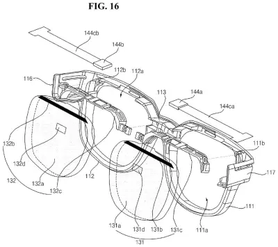
LG's patent describes a pair of glasses-shaped AR glasses with see-through lenses that show digital information in your field of view. The clever part is a separate inner frame holding your prescription lenses that snaps onto the main device using small magnets. Each lens half has a magnet with the opposite polarity, so they align and hold themselves together without screws or clips. If your prescription changes, you swap in a new inner frame.
The patent also details how the tiny display panels that project images into the lenses are mounted from the top of the frame, feeding light into a specific zone of each lens where it reflects toward your eye. A metal insert runs through the plastic nose-bridge area to keep everything stiff and in precise alignment, even if the frame flexes when you put it on or take it off.
… a light-transmissive display lens inserted into an opening formed by the main frame; a display region formed in the display lens; and an upper frame fixed to an upper side of the display lens and coupled to the main frame …
Translation: The see-through display lens fits directly into the main frame of the glasses.
How the display panel stays optically aligned inside the frame
The patent covers a wearable device shaped like eyeglasses with two key systems working together.
The display system: Each lens is made of a clear material with a small dedicated display region etched or coated into it. A tiny panel (the patent mentions micro LED, OLED, or OLEDos as options) is mounted along the top edge of the frame, pointing down at an angled incident surface on the top of each lens. Light from the panel enters the lens there and bounces off the display region toward the wearer's eye, while the rest of the lens stays transparent so you can see the real world through it. This is the waveguide-style approach used in many AR glasses.
The alignment system: A thin metal rigid piece is molded into the plastic nose bridge. The upper frames that hold the lenses fasten onto this metal insert at both ends. Because metal doesn't flex like plastic, this anchors the display panels to the lenses with consistent geometry even under daily wear stress, preventing the projected image from drifting out of position.
The prescription lens system: A separate inner subframe holds two prescription lenses and uses a pair of magnets (one N-pole, one S-pole) to attach to that same metal bridge insert inside the main frame. Because the polarities differ between left and right, the subframe self-orients when you bring it close. The whole inner frame can be removed and replaced without tools.
Circuitry, speakers, and batteries are split between the temples on each side, with batteries pushed to the tips near the ears to balance the weight of the frame.
The present invention relates to an electronic device. The electronic device may comprise: a main frame to which light-transmissive display units are attached; temples connected to the main frame; PCBs embedded in the main frame or temples …
Translation: The invention describes smart glasses built with the circuit boards hidden inside the frames and arms.
What this means for people who wear glasses and want AR
For the large share of people who need corrective lenses, most AR glasses today are a non-starter. You either wear them over your regular glasses (uncomfortable and optically imprecise) or pay for a fixed prescription build (expensive and inflexible). LG's design treats the prescription as a replaceable consumable rather than a permanent part of the device, which means your AR glasses could outlast several prescription changes.
The rigid metal insert strategy is also worth noting: keeping the display panel locked in position relative to the lens is what makes the projected image look sharp and correctly placed rather than swimming around when the frame shifts on your face. several LG filings on wearable AR hardware this year suggest the company is building out a detailed component architecture for this category, not just sketching concepts.
The sixth LG filing we cover since November, following one on preventing calculation errors and one on a spinning airport kiosk, adds another application to the pile.
Source: US 2026/0367413 A1 at the USPTO (PDF). Full patent text and figures are in the official publication.
Get our take in your Top Stories
Liked this breakdown? Add Patentlyze as a preferred source on Google, and our plain-English take shows up more often in your Top Stories the next time LG patent news breaks.
Add Patentlyze on Google
One click.
There are more where this came from
We read the new patents from Big Tech, carmakers and more and send you the ones worth knowing. Plain English, free, every week.
The drawings · 28 sheets
28 drawing sheets from US 2026/0367413 A1 · click any drawing to enlarge


Show the other 20 sheets


More from LG
All 7 LG patents →
More in AR / VR
All 718 AR / VR patents →
Snap
Snap Patents Clip-In Prescription Lenses That Click Onto AR Glasses
Microsoft
Microsoft Patents Technology to Keep AR Images the Right Size for Glasses Wearers
Meta
Meta Patents a Prescription Glasses Lens With an Eye-Tracking Camera Built Inside
Qualcomm
No comments yet