
Roborock
Roborock · Robotics · Filed Jun 30, 2026 · USPTO published Nov 19, 2026 · This week's release
Roborock Patents a Compact Spinning Mirror That Helps Robot Vacuums See Better
Roborock's patent keeps the laser and its light detector fixed and spins a small tilted mirror above them, all to make the sensor on top of a robot vacuum shorter and cheaper to build.
- Publication number
- US 2026/0367228 A1(US20260367228A1)
- Applicant
- Beijing Roborock Technology Co., Ltd.
- Filed · Published
- Jun 30, 2026 · Nov 19, 2026
- Inventors
- Bo LIU, Wei ZHANG, Bing LIANG, Jiang WU, Dan LIU
- Status when we published
- Waiting for an examiner
- Document
- 19 claims
- US classification
- 356/4.01
- Parent application
- Continuation of PCT/CN2024/142596 (filed Dec 26, 2024)(PCTCN2024142596)
What Roborock's spinning-mirror sensor does
The laser sensor that helps your robot vacuum map your home also adds to its height. The patent points out that the size of that sensor affects how big the whole machine has to be, and a bigger machine takes up more space.
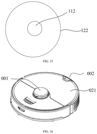
Roborock's answer is a rearrangement. The laser and the part that catches returning light stay still at the bottom. Above them, a small mirror tilted at roughly 45 degrees does the spinning. The laser beam bounces off the mirror and out through a window in the turning housing. Light that bounces back from your furniture and walls comes in through separate windows, hits the same mirror, and drops down into the detector. Spin the mirror a full circle and the robot can see all the way around itself.
The rest of the filing is about building it cheaply, such as clamping parts in place instead of gluing them.
… the reflecting mirror being obliquely disposed above the emission unit and the receiving unit, the rotating base being provided with an emission window and receiving windows, and the receiving windows being distributed on two sides of the emission window in pairs …
Translation: An angled mirror sits above the laser parts while windows on the spinning base let light in and out.
How the mirror, windows and lenses line up
This is a LiDAR, a sensor that measures distance by timing how long laser light takes to bounce off an object and come back. The claims split it into two parts. A fixed assembly holds the laser emitter and the light receiver, and neither moves. A rotating assembly sits on top and carries a mirror tilted over both of them.
Light leaves the laser, hits the mirror, and exits through a middle emission window in the spinning housing. Returning light enters through receiving windows placed in pairs on both sides of that middle window (the pictured version uses one pair), bounces off the same mirror, and lands on the receiver. A motor turns the housing, up to a full 360 degrees.
The dependent claims and the description add details:
- The mirror sits 45 to 47 degrees from horizontal.
- The laser and its lens sit in a barrel that passes through a hole in the middle of the larger receiving lens, so both share one center line.
- That barrel and lens meet in a ball-joint shape, so the laser can be aimed during assembly.
- The window over the laser is tilted (2 to 45 degrees) to stop light reflecting back into the sensor, and a narrow filter (50 nanometers or less) covers each receiving window.
The description also says a single-photon detector handles the small receiving area. Claim 19 puts the whole sensor inside a cleaning robot.
Why a shorter sensor matters for robot vacuums
If you own a robot vacuum, the sensor on top is how it maps your rooms and dodges chair legs, and its height helps set how low the machine can be. The filing says a shorter sensor lets the robot be shorter, take up less space and be easier to store.
Cost is the other thread. The description keeps swapping glue and extra screws for clamps, a pressing ring and a single locking nut, and says looser part tolerances can raise factory yield. For a home appliance sold on price, those savings are the point. The filing doesn't name a specific product.
Roborock's second patent in our home tech coverage since November follows one about lift and push detection in the two filings from this company we've tracked.
Source: US 2026/0367228 A1 at the USPTO (PDF). Full patent text and figures are in the official publication.
Get our take in your Top Stories
Liked this breakdown? Add Patentlyze as a preferred source on Google, and our plain-English take shows up more often in your Top Stories the next time Roborock patent news breaks.
Add Patentlyze on Google
One click.
There are more where this came from
We read the new patents from Big Tech, carmakers and more and send you the ones worth knowing. Plain English, free, every week.
The drawings · 8 sheets
8 drawing sheets from US 2026/0367228 A1 · click any drawing to enlarge


More from Roborock
All 7 Roborock patents →
More in Gear
All 26 Gear patents →
Roborock
Roborock Patents a Robot Vacuum With a Hard Front Brush and a Soft Rear One
Nvidia
Nvidia Patents Object Outlines That Trade Detail for Speed on Cars and Robots
Nvidia
Nvidia Files Patent for Robots That Handle Surprises They Were Never Trained On
IBM
No comments yet