
Samsung
Samsung · Cell phone · Filed Jul 16, 2026 · USPTO published Nov 19, 2026 · This week's release
Samsung Patents a Charging Port That Stays Put on a Phone With an Expanding Screen
Phones with screens that slide out have a hardware headache most people never think about: where does the charging port go when half the body moves? Samsung's answer is to cut the cable hole into the very track that guides the screen.
- Publication number
- US 2026/0370748 A1(US20260370748A1)
- Applicant
- Samsung Electronics Co., Ltd.
- Filed · Published
- Jul 16, 2026 · Nov 19, 2026
- Inventors
- Dohyeon LEE, Soohyun SEO, Sujeong CHO, Wonho LEE, Soyoung LEE
- Status when we published
- Waiting for an examiner
- Document
- 15 claims
- US classification
- 455/575.1
- Parent application
- Continuation of PCT/KR2025/001198 (filed Jan 22, 2025)(PCTKR2025001198)
What Samsung's rollable charging port actually does
You're on the couch with a phone whose screen slides out to get bigger, and the battery just hit 3 percent. You reach for the cable. On a regular phone you'd plug into the bottom edge, but here that edge is exactly where the flexible screen curls up and tucks inside the body.
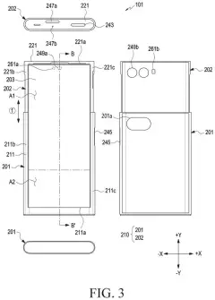
The top half is no better. It's packed with cameras, sensors and circuit boards, so there's no room for a port there either. Samsung's patent application puts the cable opening on the side of the phone instead, and routes it through the metal track that guides the screen as it slides.
The trick is picking a spot on that track that the sliding half never covers. The hole stays open to your cable whether the screen is tucked in, rolled out, or stopped somewhere in between.
… a multi-bar structure configured to support at least a portion of a surface of the flexible display; a guide rail connected to the first housing and fastened to at least a portion of the multi-bar structure to guide movement of the multi-bar structure; …
Translation: A series of tiny bars and a track work together to hold up the screen as it stretches out.
How the cable hole is cut into the rail
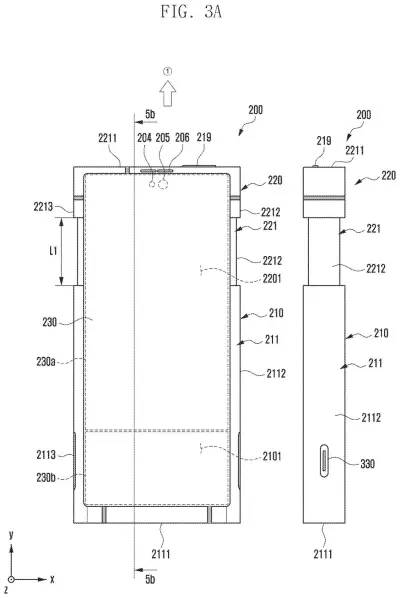
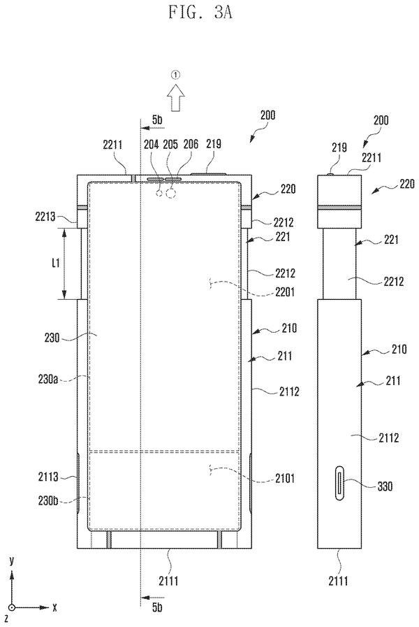
The device has two housings (the two main body halves) that slide against each other. A flexible display rides on a multi-bar structure (a chain of thin supports that bends where the screen curls inside the body and lies flat where it's visible). A guide rail fixed to the first housing steers that chain, and a guide block on the second housing slides along the rail as the halves move.
Claim 1 adds a first opening cut into the guide rail, plus a connector (the socket a cable plugs into) inside the first housing, placed so an external device can fasten to it through that opening. Dependent claims put the opening in a part of the rail the guide block never overlaps, so nothing blocks it as the halves move.
The filing also describes several extras:
- A raised lip (protrusion) on the rail around the opening, about 0.65 mm thick and 2.03 mm long in the example, which grips the plug so shaking doesn't knock it loose.
- A rubber or urethane seal (waterproofing member) around the opening to keep moisture and dust away from the connector and the flexible circuit board behind it.
- Guide members that funnel the plug through the stacked openings in the bracket, side wall and cover plates, which can be slightly misaligned by manufacturing tolerances.
- A metal rail and bracket, so electrical noise from the connector is picked up by them.
What this means for charging a rollable phone
If screens that slide out ever become everyday phones, something as ordinary as plugging in a charger has to work every time. This design keeps the port on the side and open in every screen position, so you don't have to put the screen in a certain position before you charge.
It also shows how crowded these devices are. The bottom edge belongs to the bending screen and the top is full of electronics, so even the cable hole becomes an engineering decision. The sealing and plug-gripping details show Samsung thinking about dust, moisture and a cable getting knocked loose, the everyday things that wear out gadgets.
That makes this Samsung's 98th filing we've tracked since May in our foldable phone patents watchlist, following applications like a mirror notification screen and a glass-and-plastic screen cover.
Source: US 2026/0370748 A1 at the USPTO (PDF). Full patent text and figures are in the official publication.
Get our take in your Top Stories
Liked this breakdown? Add Patentlyze as a preferred source on Google, and our plain-English take shows up more often in your Top Stories the next time Samsung patent news breaks.
Add Patentlyze on Google
One click.
There are more where this came from
We read every patent application Big Tech publishes and send you the ones worth knowing. Plain English, free, every week.
The drawings · 21 sheets
21 drawing sheets from US 2026/0370748 A1 · click any drawing to enlarge


Show the other 13 sheets


More from Samsung
All 1,662 Samsung patents →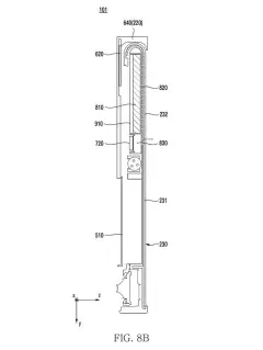
More in Cell phone
All 494 Cell phone patents →
Samsung
Samsung Files Patent for a Foldable Phone That Rests Its Cover Screen on the Battery
Samsung
Samsung Patents a Hinge That Cradles the Flexible Screen as the Phone Folds
Samsung
Samsung Files Patent to Shrink the Gap Around a Foldable Phone's Screen
Samsung
No comments yet