Get the newsletter
Samsung · Robotics · Filed Jul 24, 2026 · USPTO published Nov 19, 2026 · This week's release

Samsung Patents a Robot Mop That Drops Its Own Dirty Cloth

A mopping robot that gets rid of its own filthy cloth sounds simple, but Samsung's filing shows it takes a stopper, a ramp and a spinning plate to pull it off.
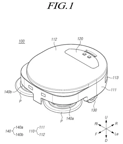
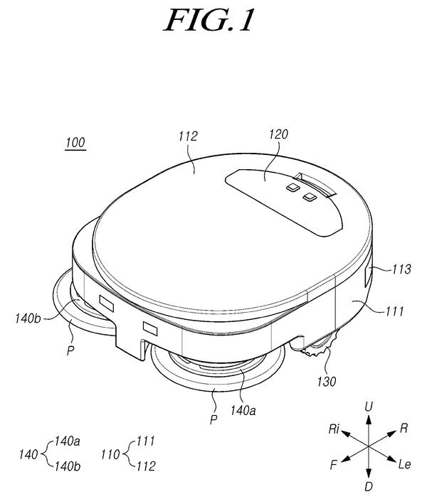
A robotic mop designed to clean floors using spinning pads mounted underneath its body. Drawing from patent filing US 2026/0363508 A1.
A robotic mop designed to clean floors using spinning pads mounted underneath its body.All 41 drawings ↓
Publication number
US 2026/0363508 A1(US20260363508A1)
Applicant
SAMSUNG ELECTRONICS CO., LTD.
Filed · Published
Jul 24, 2026 · Nov 19, 2026
Inventors
Hongseok CHOI, Elijah KIM, Juyeong KIM, Jiwon RYU
Status when we published
Waiting for an examiner
Document
8 claims
US classification
15/21.1
Parent application
Continuation of 18/535,418 (filed Dec 11, 2023)(18535418)

What Samsung's self-shedding mop cloth does

A mopping robot spins a damp cloth against your floor, and that cloth gets filthy as it goes. Once it is dirty, the robot is mostly pushing grime around, so someone has to pick it up, peel the cloth off and press on a fresh one. Samsung's patent application describes a robot that does that swap by itself.

The trick is a two-part plate on the bottom of the robot. The cloth sticks to the upper part, using magnets or hook-and-loop fasteners (the Velcro kind). When it is time to let go, the robot lowers a small stopper into a slot on that upper part. The stopper holds it still while the lower plate keeps turning, and a little ramp slowly lifts the upper part away, so the cloth drops off.

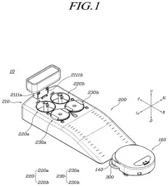
The filing also describes the robot rolling to a spot you choose, or to its charging dock, to drop the old cloth and pick up a new one.

From the filing · CLAIM 1
… a separation driver including a stopper configured to move up and down; and a cleaning cloth module including: a first member including an attaching member to which a cleaning cloth is detachably couplable, and a second member configured to be rotated by the motor …

Translation: A mechanical stopper moves up and down to detach the dirty cloth while the inner part keeps spinning.

How a small stopper pries the cloth loose

The claimed robot cleaner has a housing, a motor, a separation driver with a stopper that moves up and down, and a cleaning cloth module built in two pieces. The first member carries the attaching member (magnets or Velcro in the description) that holds the cloth. The second member sits between the first member and the cloth, and the motor spins it.

During mopping, the two pieces are coupled and turn together. To release the cloth, the stopper moves down and stops the first member from rotating. The motor keeps turning the second member, which slides along an inclined portion (a small ramp) on the underside of the first member. That sliding widens the gap between the two pieces, and the cloth comes free.

The description adds supporting details:

  • One motor can drive both the spinning cloth and the stopper through a shared gear assembly. The motor's turning direction decides whether the stopper rises or falls.
  • A lifting mechanism can raise the cloth module off the floor before the release.
  • Springs pull the two members back together when a fresh cloth is mounted.
  • A controller flags a replacement using a contamination sensor or a use timer, such as a user-set one hour cycle.

In the examples, the robot drives to a spot the user picks, such as next to the bathroom, or to a dock holding fresh cloths and a bin for used ones.

What this means for hands-off floor mopping

If a design like this ever reached a product, changing a dirty mop pad would come off your to-do list. The robot would finish a stretch of mopping, roll to its dock, drop the used cloth and pick up a clean one. The filing itself says the goal is to replace the cloth without the user's intervention.

A patent application is not a product, and nothing here says when or whether it ships. The design also leans on a gear train, springs, a threaded stopper and a dock with a supply of cloths. The filing does not say how that mechanism holds up after months of wet, grimy use, so durability is an open question.

This is the 60th Samsung filing we've tracked in our home robots watchlist since May, building on work like a self-straightening vacuum mop and a moving dock nozzle.

Source: US 2026/0363508 A1 at the USPTO (PDF). Full patent text and figures are in the official publication.

Get our take in your Top Stories

Liked this breakdown? Add Patentlyze as a preferred source on Google, and our plain-English take shows up more often in your Top Stories the next time Samsung patent news breaks.

There are more where this came from

We read every patent application Big Tech publishes and send you the ones worth knowing. Plain English, free, every week.

The drawings · 41 sheets

41 drawing sheets from US 2026/0363508 A1 · click any drawing to enlarge

Samsung robot mop carrying two spinning cleaning pads, drawing sheet 1 from US 2026/0363508 A1
Sheet 1 Samsung robot mop carrying two spinning cleaning pads
Underside view of the drive wheels and mop discs, drawing sheet 2 from US 2026/0363508 A1
Sheet 2 Underside view of the drive wheels and mop discs
Electronic parts that decide when to swap dirty mop pads, drawing sheet 3 from US 2026/0363508 A1
Sheet 3 Electronic parts that decide when to swap dirty mop pads
Motor assembly that spins and releases a cleaning pad, drawing sheet 4 from US 2026/0363508 A1
Sheet 4 Motor assembly that spins and releases a cleaning pad
Internal gears that drive the mop and release pin, drawing sheet 5 from US 2026/0363508 A1
Sheet 5 Internal gears that drive the mop and release pin
Central shaft mechanism that lifts and lowers the mop disc, drawing sheet 6 from US 2026/0363508 A1
Sheet 6 Central shaft mechanism that lifts and lowers the mop disc
Cross section of the spring loaded pad release disc, drawing sheet 7 from US 2026/0363508 A1
Sheet 7 Cross section of the spring loaded pad release disc
Stacked parts that grip and let go of the cloth, drawing sheet 8 from US 2026/0363508 A1
Sheet 8 Stacked parts that grip and let go of the cloth
Show the other 33 sheets
Bottom parts that hold and release the mop pad, drawing sheet 9 from US 2026/0363508 A1
Sheet 9 Bottom parts that hold and release the mop pad
Forward spinning keeps the mop locked onto the floor, drawing sheet 10 from US 2026/0363508 A1
Sheet 10 Forward spinning keeps the mop locked onto the floor
Reversing rotation directs a pin into the lift track, drawing sheet 11 from US 2026/0363508 A1
Sheet 11 Reversing rotation directs a pin into the lift track
Upward movement begins as the pin climbs the internal slot, drawing sheet 12 from US 2026/0363508 A1
Sheet 12 Upward movement begins as the pin climbs the internal slot
Continued reverse spinning pulls the mop plate higher, drawing sheet 13 from US 2026/0363508 A1
Sheet 13 Continued reverse spinning pulls the mop plate higher
Arriving at the top raises the pad for travel, drawing sheet 14 from US 2026/0363508 A1
Sheet 14 Arriving at the top raises the pad for travel
Locking the pin keeps the mop raised off ground, drawing sheet 15 from US 2026/0363508 A1
Sheet 15 Locking the pin keeps the mop raised off ground
Slotted plates twist together to push the dirty pad away, drawing sheet 16 from US 2026/0363508 A1
Sheet 16 Slotted plates twist together to push the dirty pad away
Curved slots let gripping pads retract into the mop disc, drawing sheet 17 from US 2026/0363508 A1
Sheet 17 Curved slots let gripping pads retract into the mop disc
Angled ramps pull cloth grippers upward when the discs twist, drawing sheet 18 from US 2026/0363508 A1
Sheet 18 Angled ramps pull cloth grippers upward when the discs twist
A retractable peg catches the disc to release a cloth, drawing sheet 19 from US 2026/0363508 A1
Sheet 19 A retractable peg catches the disc to release a cloth
Internal parts of the peg assembly that halts mop rotation, drawing sheet 20 from US 2026/0363508 A1
Sheet 20 Internal parts of the peg assembly that halts mop rotation
Motor gears that spin and lift the cleaning pad, drawing sheet 21 from US 2026/0363508 A1
Sheet 21 Motor gears that spin and lift the cleaning pad
Normal cleaning position with the mop pressed to the floor, drawing sheet 22 from US 2026/0363508 A1
Sheet 22 Normal cleaning position with the mop pressed to the floor
Raising the mop disc to start dropping the dirty cloth, drawing sheet 23 from US 2026/0363508 A1
Sheet 23 Raising the mop disc to start dropping the dirty cloth
Lowering the lock pin stops the plate to eject pads, drawing sheet 24 from US 2026/0363508 A1
Sheet 24 Lowering the lock pin stops the plate to eject pads
Lowering the mop head to press onto a clean pad, drawing sheet 25 from US 2026/0363508 A1
Sheet 25 Lowering the mop head to press onto a clean pad
Inside an alternative mop driver that releases pads, drawing sheet 26 from US 2026/0363508 A1
Sheet 26 Inside an alternative mop driver that releases pads
An assembled alternative mop pad holder and spindle, drawing sheet 27 from US 2026/0363508 A1
Sheet 27 An assembled alternative mop pad holder and spindle
Top view of the alternative mop head parts laid bare, drawing sheet 28 from US 2026/0363508 A1
Sheet 28 Top view of the alternative mop head parts laid bare
Bottom view showing the gripping pads and screw mounts, drawing sheet 29 from US 2026/0363508 A1
Sheet 29 Bottom view showing the gripping pads and screw mounts
The motorized pin that drops down to lock the plate, drawing sheet 30 from US 2026/0363508 A1
Sheet 30 The motorized pin that drops down to lock the plate
Exploded parts of the pin mechanism that halts rotation, drawing sheet 31 from US 2026/0363508 A1
Sheet 31 Exploded parts of the pin mechanism that halts rotation
Readying the alternative mechanism to detach a cloth, drawing sheet 32 from US 2026/0363508 A1
Sheet 32 Readying the alternative mechanism to detach a cloth
Raising the mop disc to start detaching a pad, drawing sheet 33 from US 2026/0363508 A1
Sheet 33 Raising the mop disc to start detaching a pad
Lowering the pin to lock the mop plate in place, drawing sheet 34 from US 2026/0363508 A1
Sheet 34 Lowering the pin to lock the mop plate in place
Retracting the gripping teeth to release the dirty pad, drawing sheet 35 from US 2026/0363508 A1
Sheet 35 Retracting the gripping teeth to release the dirty pad
Dropping the dirty pad away from the mop, drawing sheet 36 from US 2026/0363508 A1
Sheet 36 Dropping the dirty pad away from the mop
Using a magnetic ring to guide pad release, drawing sheet 37 from US 2026/0363508 A1
Sheet 37 Using a magnetic ring to guide pad release
Engaging the magnetic ring to control the mop disc, drawing sheet 38 from US 2026/0363508 A1
Sheet 38 Engaging the magnetic ring to control the mop disc
How the robot decides when to swap cleaning pads, drawing sheet 39 from US 2026/0363508 A1
Sheet 39 How the robot decides when to swap cleaning pads
Returning to a dock to pick up fresh pads, drawing sheet 40 from US 2026/0363508 A1
Sheet 40 Returning to a dock to pick up fresh pads
Swapping mop pads at the docking station, drawing sheet 41 from US 2026/0363508 A1
Sheet 41 Swapping mop pads at the docking station
Patent filing page

Watchlists this filing belongs to

All watchlists →
Reader comments

No comments yet

Start the discussion

Real name or a handle, either is fine. Comments are read by a person before they appear, so allow a little time. Keep it about the filing.